Smart Connector Operator’s Guide
This guide is intended for use with 2026.0.0 and its variants. Guides for older versions of Gen 3 20|20 software may be found at cloud.precisionplanting.com.
 Contents
- Smart Connector Requirements
- Home and Control Screens
- Equipment Setup
- System Setup
- Hardware Setup
- System Settings
- Alerts
- Changing Crop
- Using Hybrids
- Diagnostics
 Smart Connector Requirements
20|20 System Requirements
- Seeding system configured on the 20|20.
- System Control widget enabled.
- Target Population set.
- Speed source active.
20|20 System Recommendations
- Lift Switch configured / calibrated. 20|20 will alarm when lifted without a lift switch.
- Default Population set. 20|20 will use this value for out-of-prescription alerts / alarms.
 Major Changes
2026.0.0 software introduces many changes to system organization. High-profile changes related to Smart Connector are detailed here.
Active Crop / Hybrid
Active Crop is now selected on the Field Setup screen, and Hybrids are set up in the Products menu. See Using Hybrids and Changing Crop in this guide for more details.
Crop Settings
Some Equipment and System settings are designated as Crop Settings, indicated by the Crop Setting icon ![]() .
.
All Crop Setting changes will be saved to the current Active Crop. After switching from a new crop back to any other previous crop, all Crop Settings will revert to the last saved value for that crop. See Crop Settings for more details.
 Home and Control Screens
Home Screen
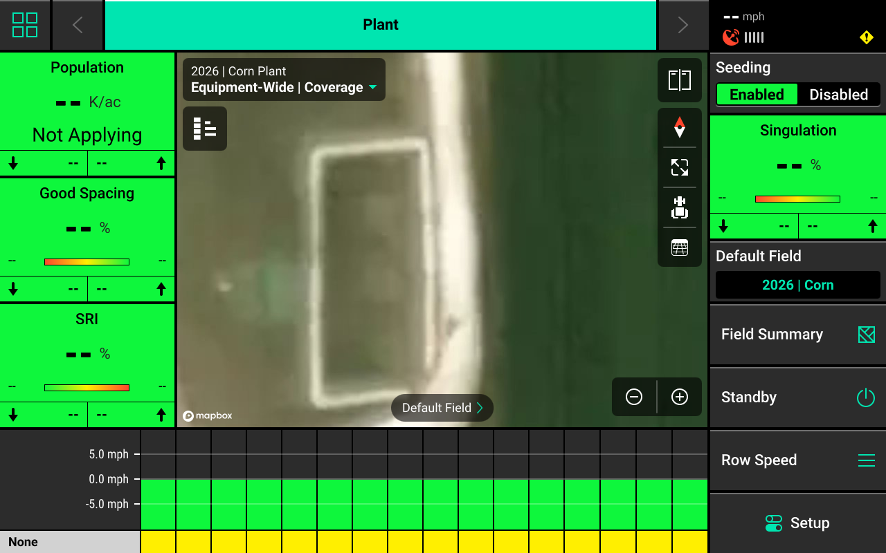
The home screen displays information for controlling and mapping the Smart Connector.
Smart Connector Mapping
Different maps are available for the Smart Connector system. To view the map layer options, press the current layer name that is displayed in the top left corner of the map. A popup list of all available maps will be displayed.
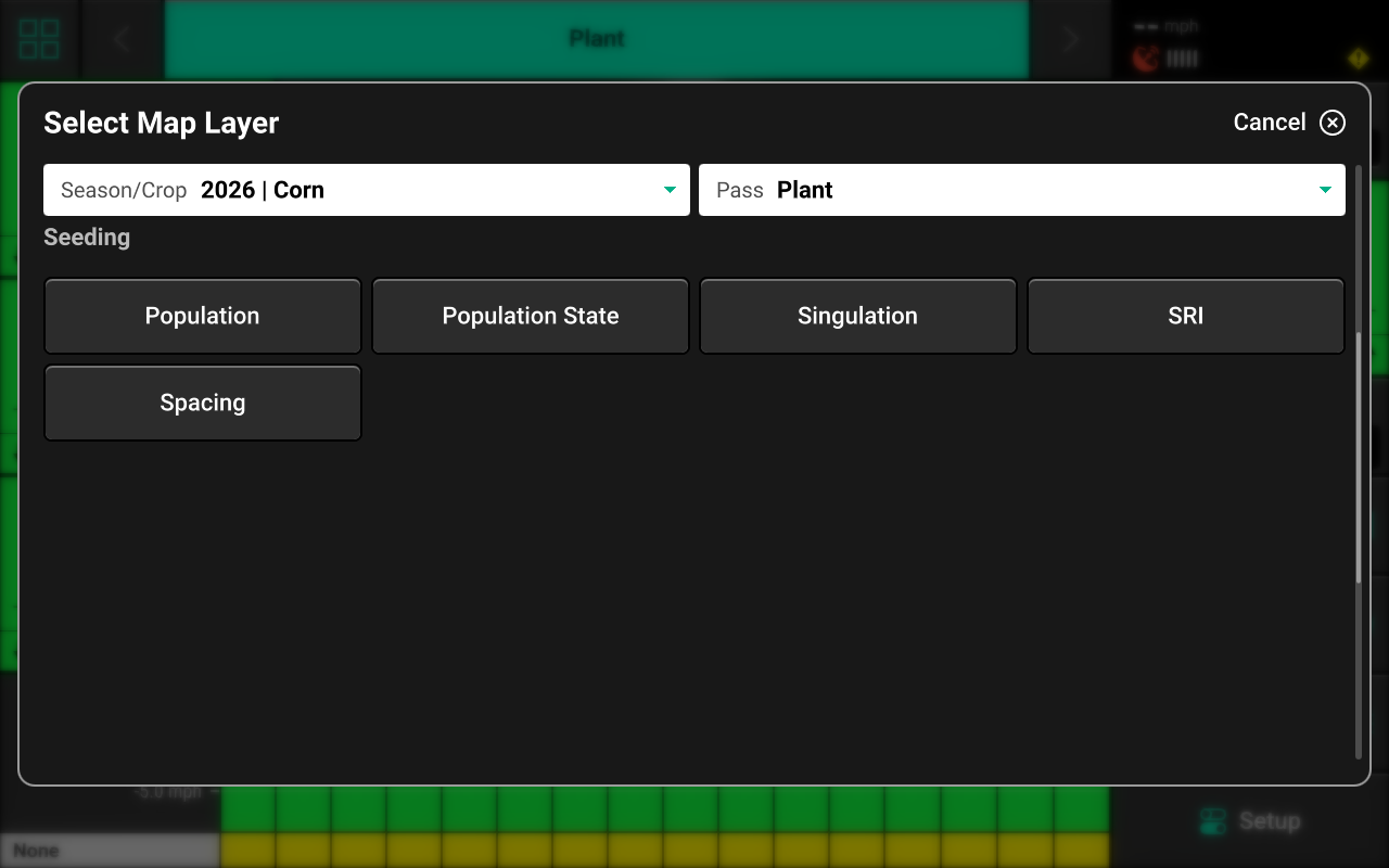
- Population — Displays planted population.
- Population State — Displays alert / alarm readings.
- Singulation — Displays seed singulation results.
- SRI — Displays Seed Release Index readings.
- Spacing — Displays average seed spacing.
If a seeding prescription is assigned to the active field, the prescription file will be available as a map layer.
See the 2026.0.0 Gen 3 Operator's Guide for definitions of these and other metrics and for more information on using the map.
Control Widget
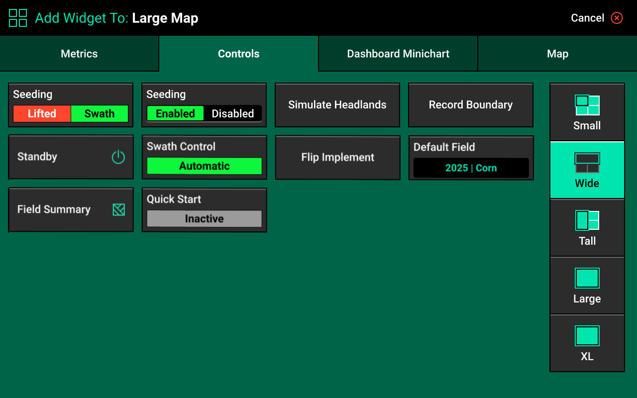
A Control widget for the Smart Connector system must be placed on the home screen and enabled before the system will function. Press the Four Squares in the top left, then press Add Widget + in the bottom right and select Controls to view options. Some Control widgets include a toggle which allows the user to enable or disable the system without opening the Control screen. Other control widgets include quick adjust buttons for population change. Press the different sizes on the right to view all options.
The term "Control Widget" refers to Enabling / Disabling the system in the 20|20 monitor. Every system requires a control widget, even if the the physical seeding motors / drives are operated by a third party. For systems utilizing a Rate Control Module to control hydraulic seeding motors through the 20|20, see Rate / Swath Control Screen in the Rate Control / Swath Module Operator's Guide.
Control Indicators
- Enabled : The system is prepared to operate.
- Disabled : The system will not operate / read seed data. To enable the system, toggle the system to enabled using the control widget.
- Lifted : The system will not plant due to lift switch reading.
- Master Off : The master plant switch on the CCM is off or the safety warning was bypassed. The system will not plant. This status will not display if the 20|20 is not operating the physical motors / drives or any other application hardware.
- Sensor : The system is using a sensor (e.g. SmartFirmer) for population control. Not used for sensing-only systems.
Control Screen
Once the Control widget has been added to the Home Screen, press it to open the Control screen.
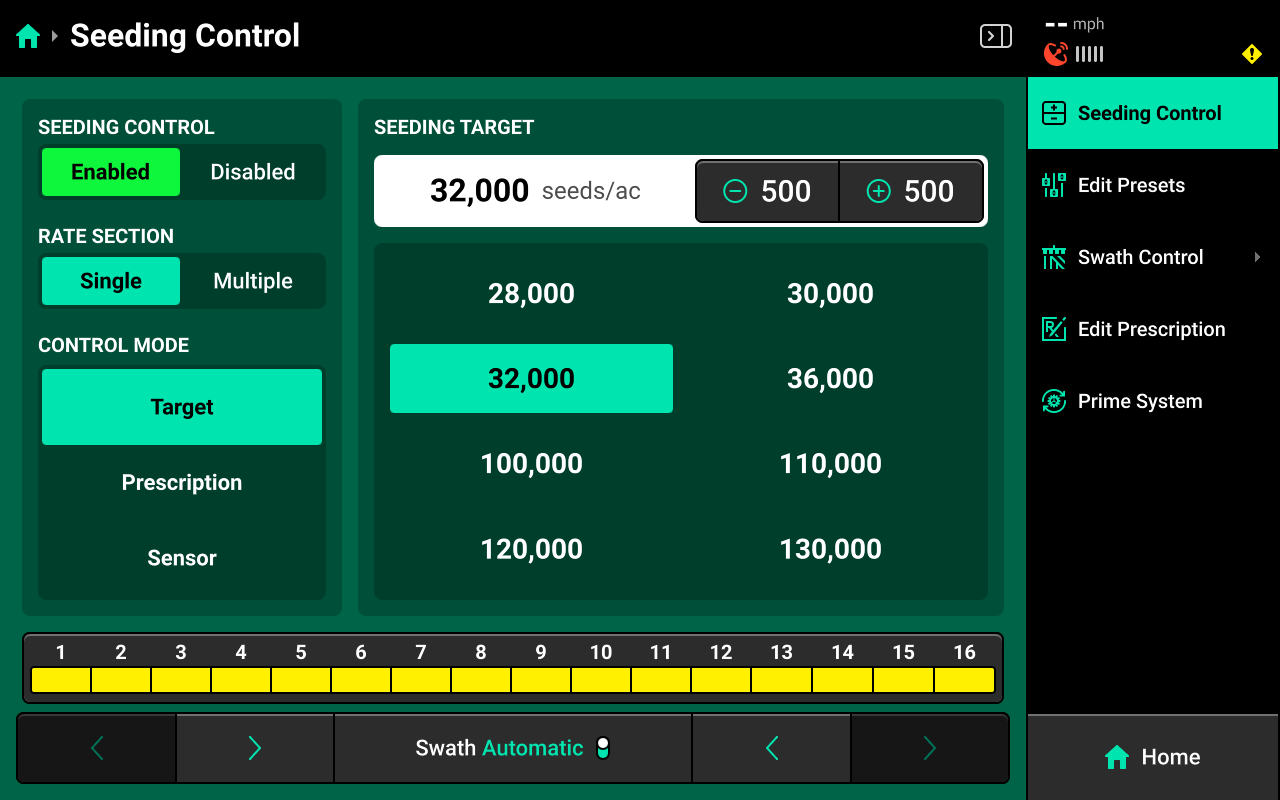
Control Mode
Select the desired Control Mode to set the target population manually, by prescription, or by SmartFirmer readings.
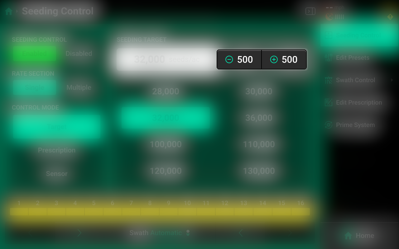
Target Control
Allows the user to manually select target population for one or more rate sections. This setting ignores any assigned prescriptions. The system will automatically adjust alerts / alarms to the target based on inputs such as speed and row spacing.
Rate Sections
- Single : One population across all rows.
- Multiple : Up to 4 different populations across preconfigured sections of the planter. See System Settings for more details. For sensing-only systems, 20|20 rate sections must mirror third party rate sections.
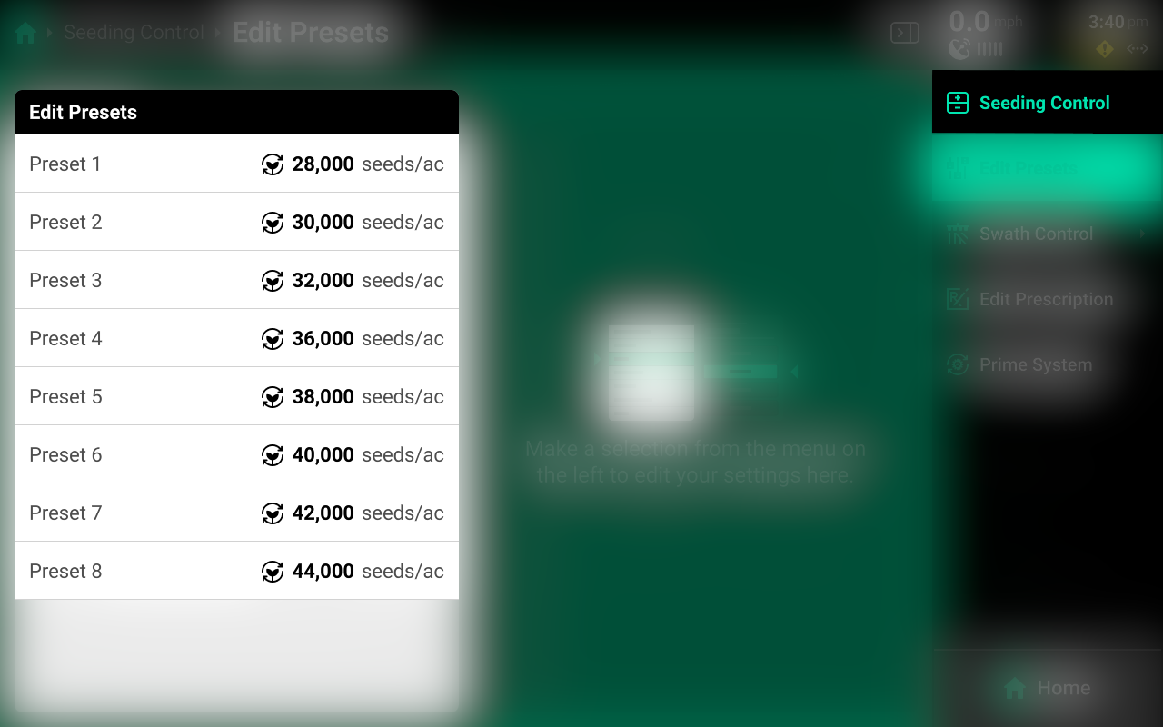
Select the desired Rate Section mode and set the desired population(s) using the presets in the center. Press the number displayed under Seeding Target in the center to manually enter a target population (Single rate section only). Press Edit Presets on the right to modify the table of preset population values.
Multiple Rate Sections are only available when using Target control mode.
Prescription Control
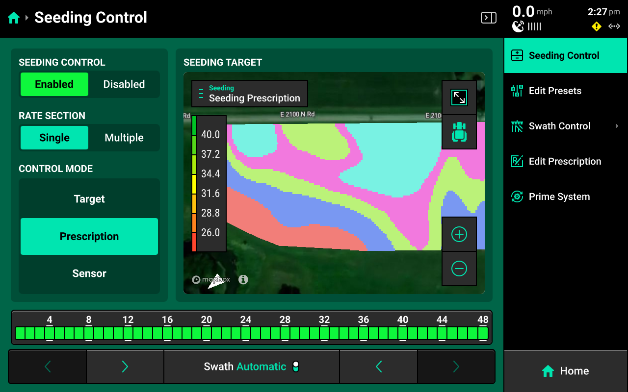
Sets the system to alert / alarm using the prescription assigned to the active field. A map of the prescription will be displayed in the center. Press Edit Prescription in the navigation menu to open the prescription edit screen.
Edit Prescription
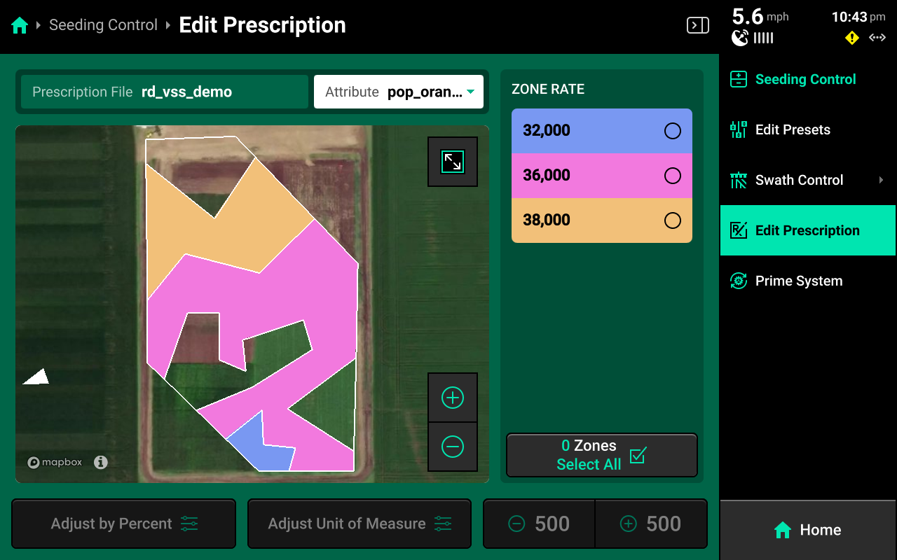
Select the desired prescription attribute to edit using the dropdown box above the map, then select the desired zone rates and use the buttons at the bottom to adjust those rates by a percent or by a preset value. Press Adjust Unit of Measure to switch between Imperial and Metric measurements for the selected zones.
Sensor Control
Used to control rate to SmartFirmer readings. Not used for sensing-only systems.
 Equipment Setup
Modules
The Smart Connector must be added as a CAN Module to function. To configure CAN modules, navigate to Setup > Equipment > Planter > Modules. If the 20|20 is connected to the implement, "(X) Unconfigured CAN Bus Modules" will be displayed in the lower right. Press Configure Planter, also in the lower right, to open the Module setup wizard.
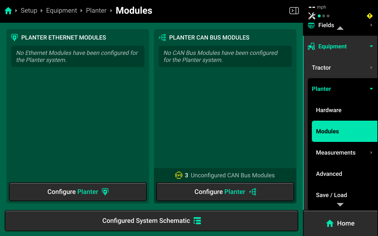
Use the tabs at the top of the screen to configure each used CAN bus on each step of the wizard if necessary. Any CAN Bus which has detected modules will show an indicator icon ![]() next to the CAN bus name.
next to the CAN bus name.
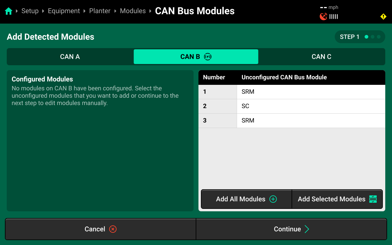
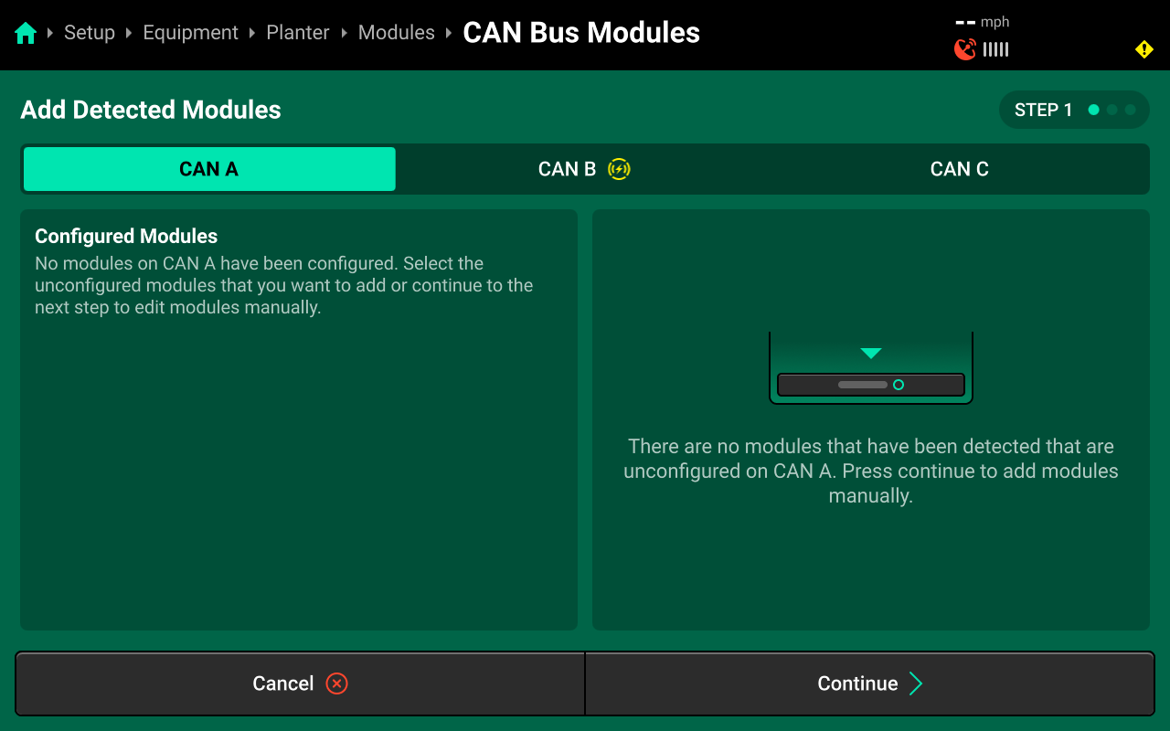
Each step of the wizard will start on CAN A. Ensure to select the correct CAN bus(es) on each step. All systems utilizing the Single CAN Sensing Harness (725935) will skip CAN A on each step and be set up entirely on CAN B.
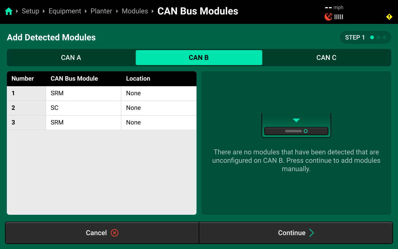
If the 20|20 is not connected to the implement, or there are no detected CAN modules on the selected CAN bus, the right window will be empty.
On Step 1, if the Smart Connector is detected correctly in the right window, press Add All Modules+ in the lower right to confirm and save detected CAN bus sequence. All detected modules will then move to the left window. If the Smart Connector is not physically plugged in to the 20|20, skip this step and configure it manually on Step 2. Press Continue to advance.
If the Smart Connector was detected correctly on Step 1, skip Step 2.

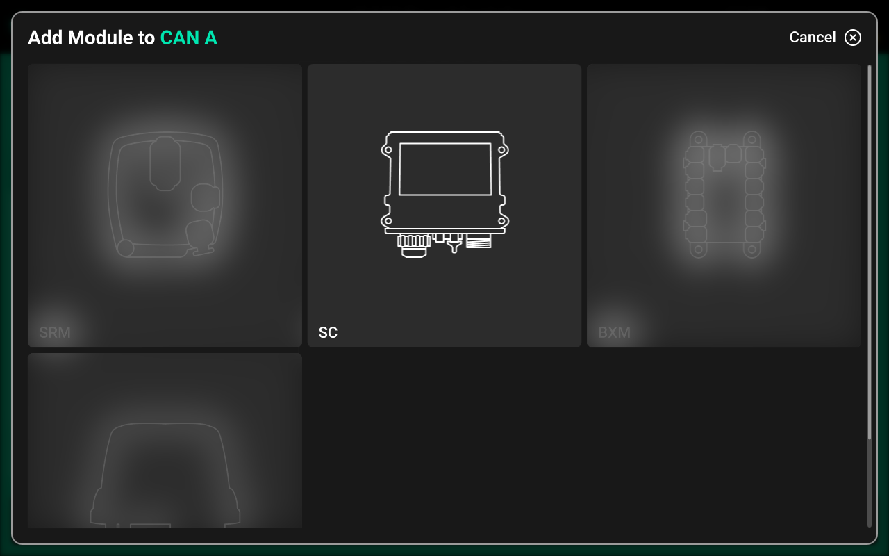
When setting up CAN bus sequence manually on Step 2, if CAN Modules other than the Smart Connector (e.g. SRM) will be connected to the 20|20, all CAN modules must be set up in the correct sequence. If the CAN bus sequence is set up incorrectly, the system will not function when the CAN bus is plugged in to the 20|20. Smart Connector systems will typically have at least one SRM installed.
Use Step 2 to set up the CAN Bus sequence manually if necessary. Press Add Module+ in the right window. Select Smart Connector (SC) from the popup and enter the number of Smart Connectors in sequence (typically 1). Press Continue to advance.
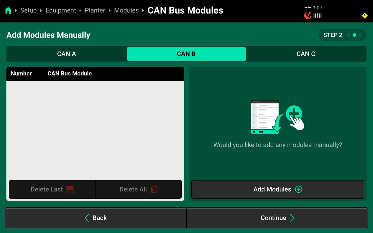
Use Step 3 to assign the CAN Bus location to each CAN Module. For Smart Connector systems, CAN Bus location will not necessarily align with CAN sequence from Steps 1 & 2, so each location must be set manually instead of using the Auto-Assign feature.
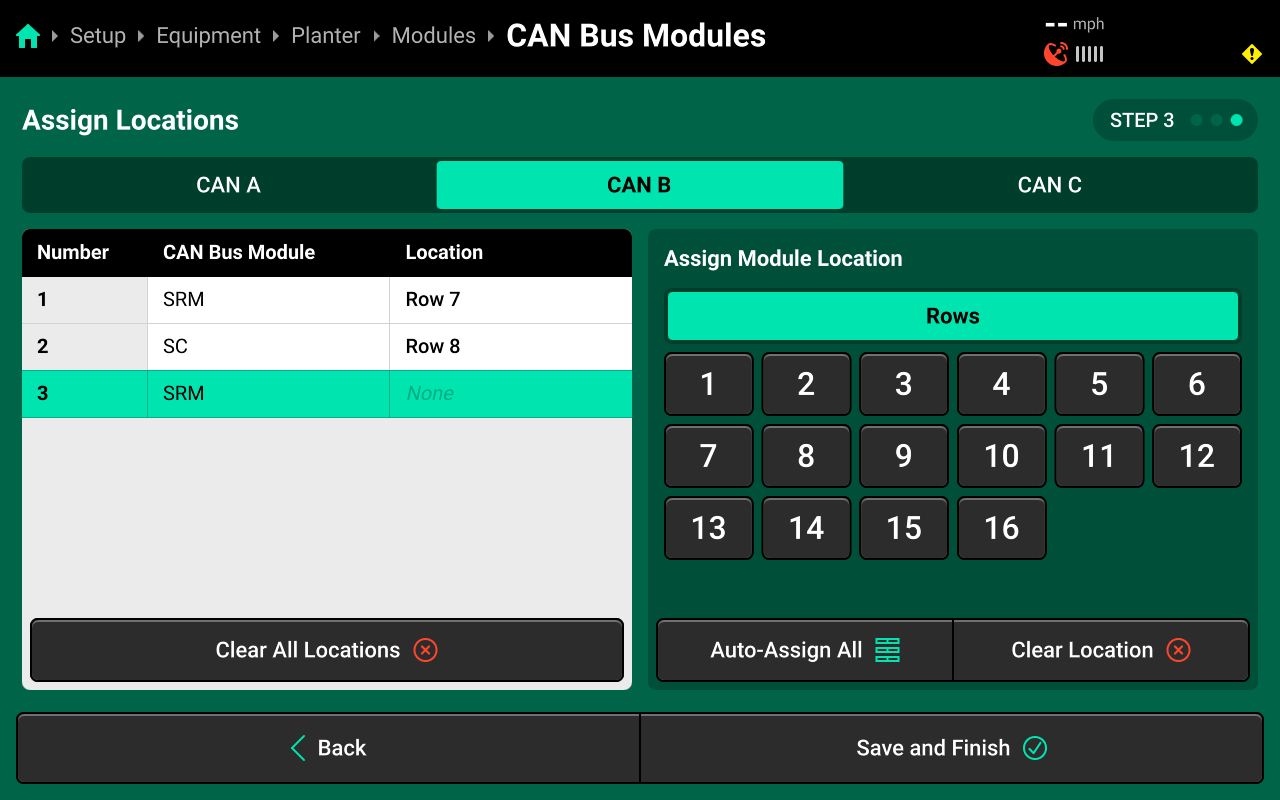
Press on each CAN module in the left window, then select a location from the table in the right window to assign that location to the selected module. Press Save and Finish to exit the wizard.
All Smart Connectors must be assigned a Row location, even if the module is physically mounted on the frame. For ease of diagnostics, it is recommended to pick a row that is closest to the physical module.
 System Setup
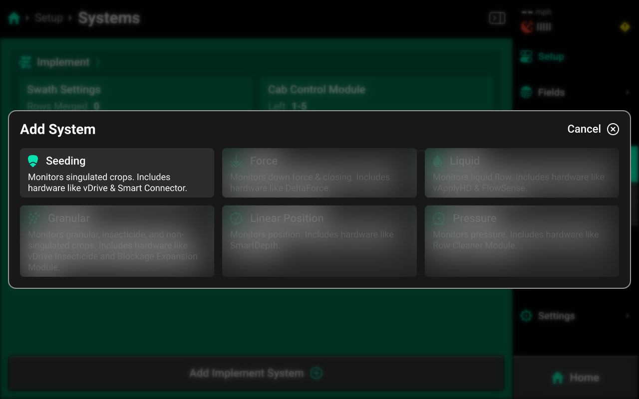
The Smart Connector requires a Seeding-type System to be configured in the 20|20. To configure a seeding system, navigate to Setup > Systems and press Add Implement System in the bottom center.
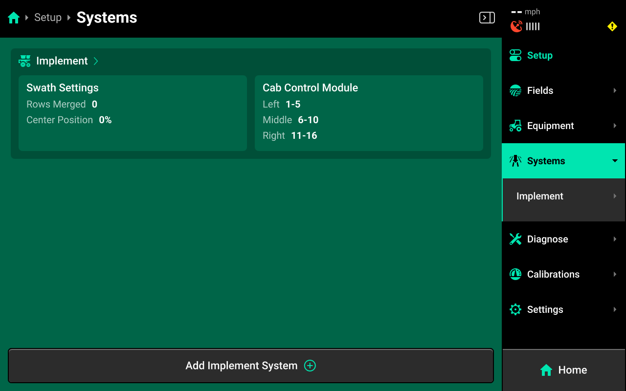
Select Seeding from the popup, then select a preset name or enter a custom name from the second popup.
 Hardware Setup
This guide assumes that all implement wide hardware (e.g. lift switches, SmartFirmers) are already configured.
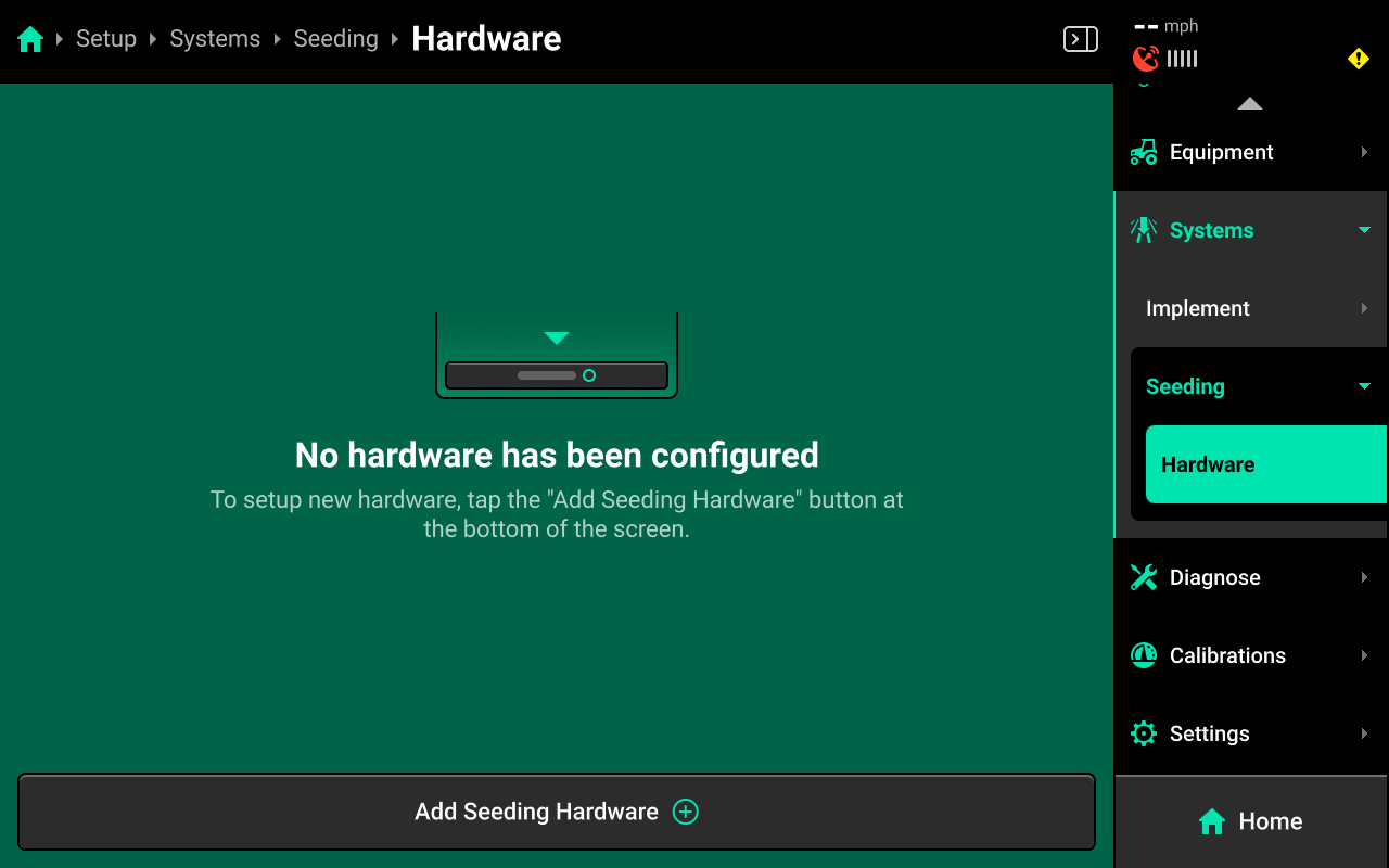
To configure Smart Connector hardware, select [Seeding System Name] in the Navigation Menu, then press Hardware under that system and use the following process.
Smart Connector
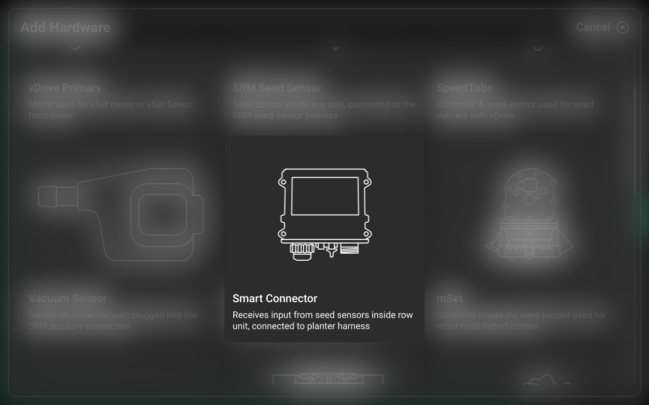
Press Add [System Name] Hardware + and select Smart Connector from the popup to open the Smart Connector hardware setup wizard.
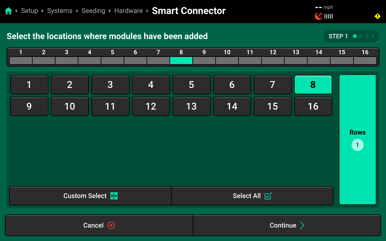
On Step 1, select the row(s) that were chosen in CAN Module setup as the Smart Connector location, then press Continue.
This step defines the location of the Smart Connector, not the seed tubes. Do not select all rows. Select the same row that was assigned to the Smart Connector on Step 3 of CAN Module setup.
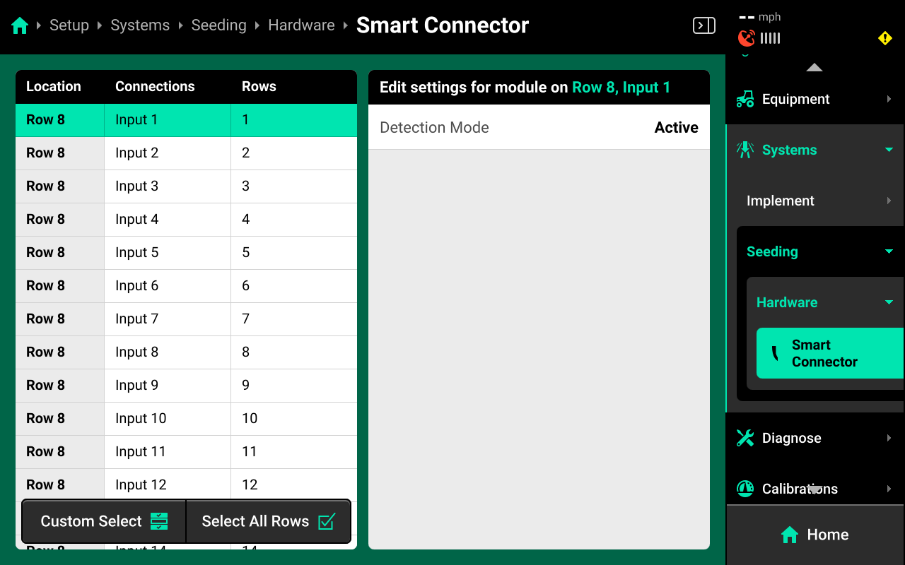
On Step 2, use the right window to select the Smart Connector pins, or inputs, which are being used. For typical installations, this will correspond to the number of rows on the planter.
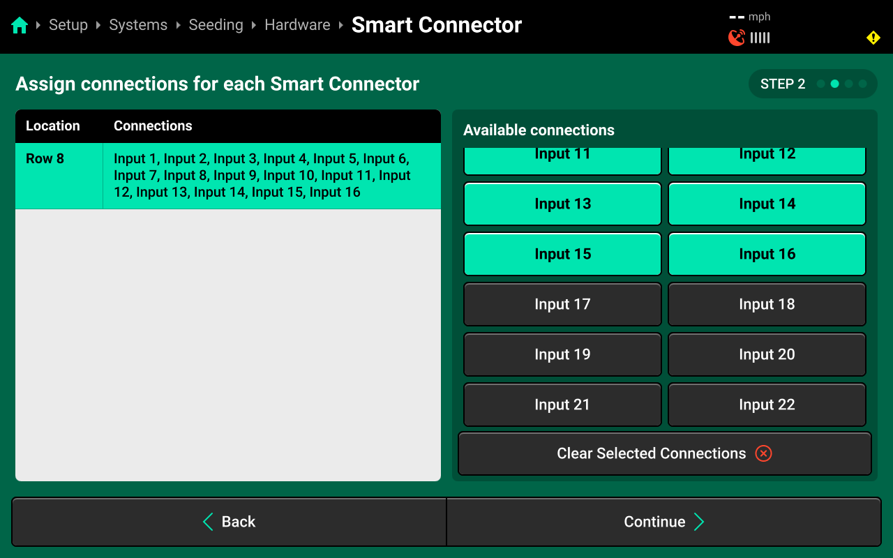
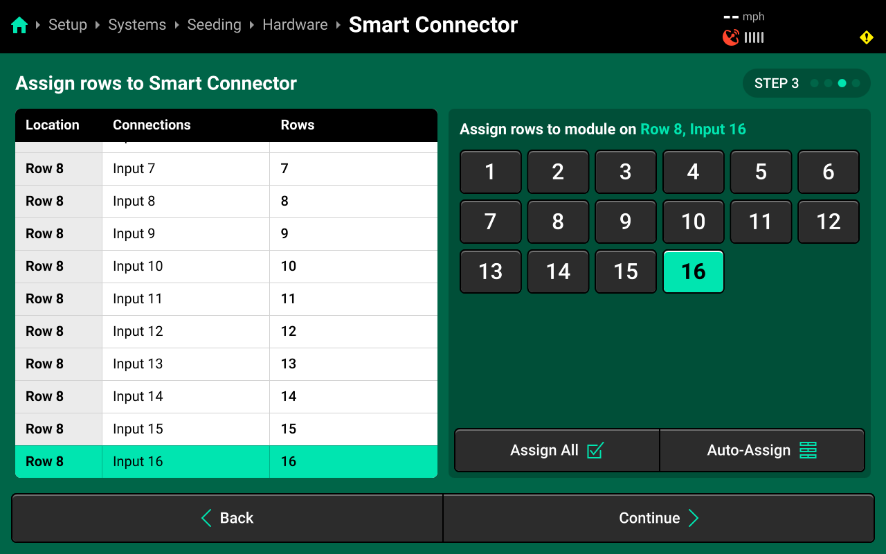
On Step 3, press Auto-Assign in the lower right to assign each a row to an input sequentially for all typical installations. For non-typical installations or custom planter harnesses, select each input in the left window, then select the correct row that input is monitoring in the right window.
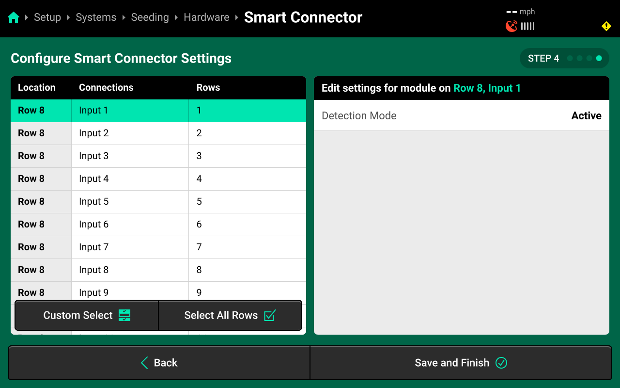
On Step 4, use the left window to select all inputs, then use the right window to change the desired hardware setting. Press Save and Finish to exit setup.
Hardware Settings
Detection Mode
Set Detection Mode to Passive if the seed sensors are not powered by the 20|20. This is required on all JD EE planters. Otherwise, leave this setting on Active.
If changing detection mode to passive, ensure to press Select All Rows in the bottom left before changing the setting. Otherwise only the selected input (likely Input 1) will be changed to Passive.
Modifying Hardware
All configured hardware devices will appear on the Hardware screen for each system. Press the ![]() Icon on each device to delete it, or Edit Locations to run through the setup wizard again.
Icon on each device to delete it, or Edit Locations to run through the setup wizard again.
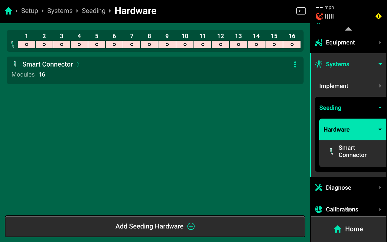
After configuring a hardware device, that device will appear under Hardware for that system in the Navigation Menu. Press any hardware device to view the settings from the final step of the setup wizard.
 System Settings
After hardware setup is complete, press [Seeding System Name] in the Navigation Menu to adjust system settings.
Additional options will be available after hardware setup is complete. View all options by scrolling on the list.
Select a setting in the left window and modify the setting using the right window.
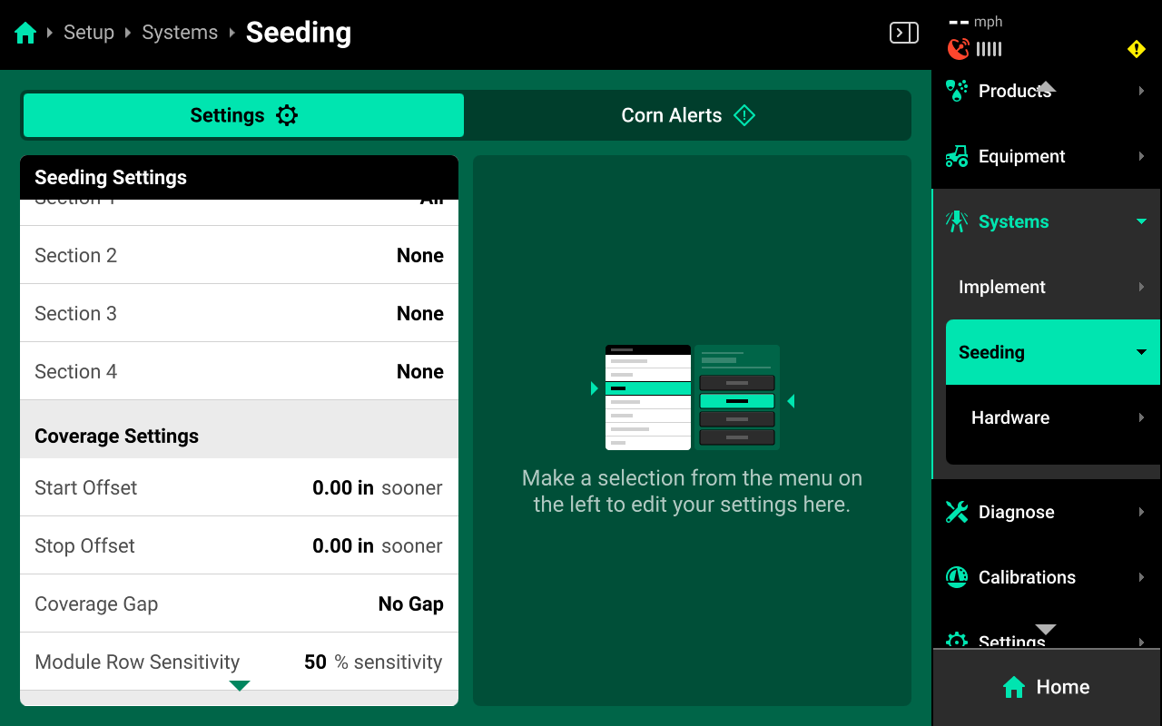
- Control Sections : Used to set up different rate sections. Select a preset number of rows for each section or use Custom to assign rows manually. Control sections are system-specific. The rates for each control section are adjustable individually or collectively using the system Control widget on the home screen.
- Start / Stop Offset : Not used with sensing-only systems.
- Coverage Gap : Not used with sensing-only systems.
- Module Row Sensitivity : Not used with sensing-only systems.
- CCM Autoload : Not used with sensing-only systems.
- Coverage Method : Used to determine when the 20|20 will build Coverage. Any system set to Work State and Applying will not map Coverage unless the lift switch reads lowered. Population and other application maps will still build.
- Active Rows : Sets the active rows for the system. System hardware on any rows not set to active will be deactivated. This setting will typically not be adjusted. To adjust active rows (e.g. when switching from corn to beans on a split-row planter), use Active Rows in the planter profile at Setup > Equipment > Planter.
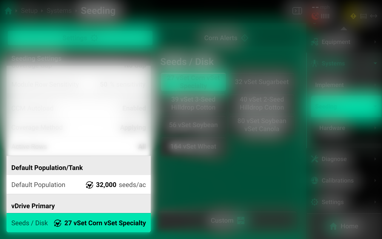
- Default Population : Sets the out-of-prescription alert / alarm thresholds for Smart Connector.
 Alerts
Use the tab at the top of [Seeding System Name] to view the crop-specific alerts for the system. Some alerts are adjustable by default, others require the corresponding hardware to be added first. It is advised to add all system hardware before configuring alerts for ease of use. All crops have the same default alert settings, but any changes made will be saved to the specific crop. Press Restore Defaults at the bottom to reset crop alert settings.
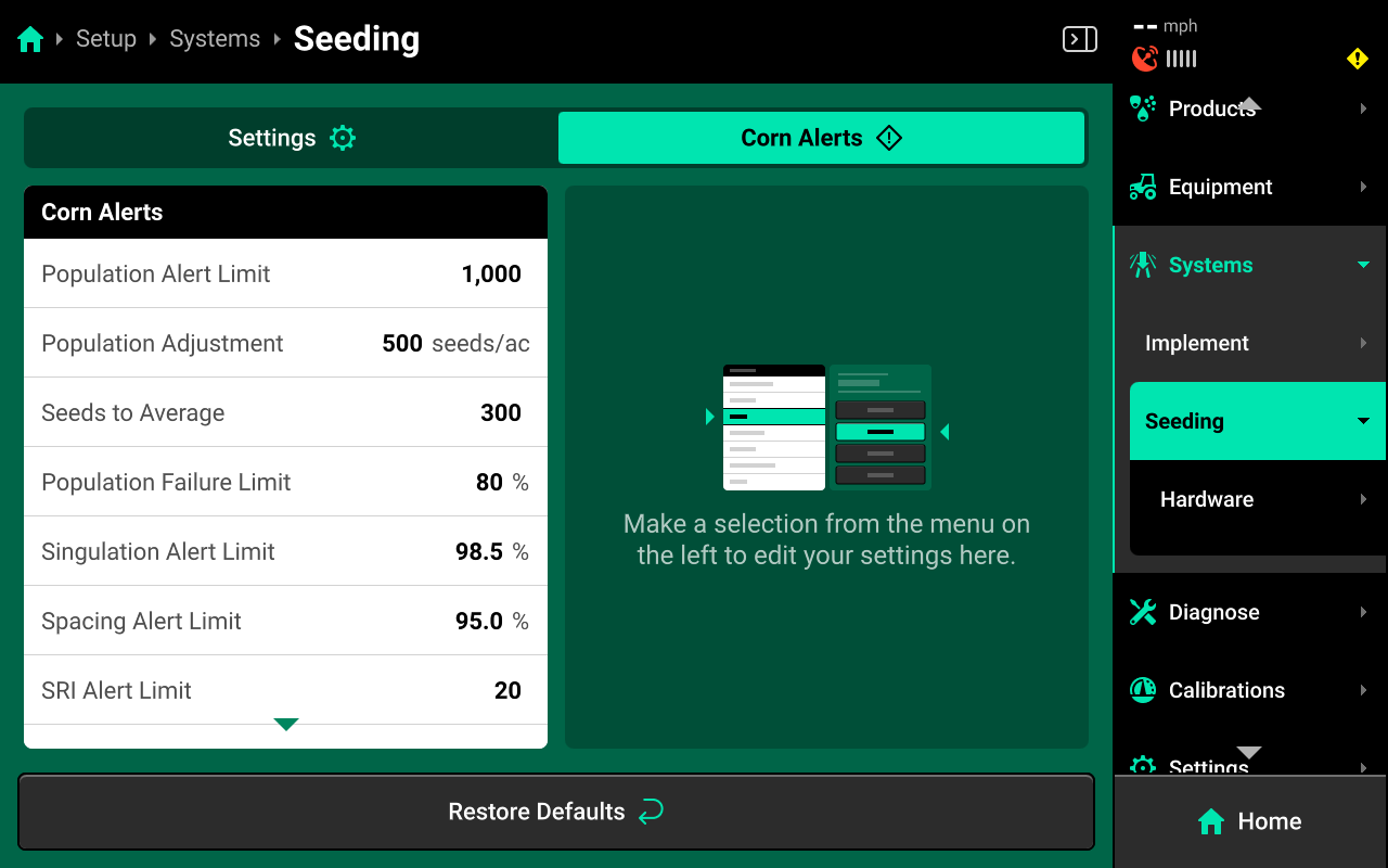
Some alerts contain both Alert and Failure limits. The 20|20 will display a popup notification when alert limits are reached, and will perform the action selected for Failure Action when failure limits are reached.
For Smart Connector systems, the thresholds for all Alerts correspond to the value that the seeds sensors are reading compared to the target population.
Optical seed sensors may be affected by physical conditions such as dust and light.
Use the left window to select an alert and the right window to modify its paramters.
- Population Alert Limit : Sets the percent difference from commanded population at which the 20|20 will deliver an alert.
- Population Adjustment : Sets the value by which the quick adjust buttons on the seeding system control screen will adjust population.
- Seeds to Average : Sets the value which the 20|20 will use when calculating the rolling average for population, singulation, spacing, and SRI. It is recommended to use a value that corresponds to 1% of population (e.g. If planting with a population of 30,000, use a Seeds to Average value of 300.).
The 20|20 uses Seeds to Average to compute / display population using seed tube pulses and other inputs. When a third party is controlling seeding, short delays in population adjustments on the 20|20 may be experienced when the third party system changes rate as the rolling average calculates. Reducing the seeds to average below recommendation will result in erratic readings since the system will continually be recalculating.
- Population Failure Limit : Sets the percent difference from commanded population at which the 20|20 will deliver a failure alarm.
- Singulation Alert Limit : Sets the singulation percent at which the 20|20 will deliver an alert. Singulation refers to the percentage of time that the 20|20 detects the release of one seed, rather than a skip or multiple.
- Spacing Alert Limit : Sets the seed spacing percent at which the 20|20 will deliver an alert. Spacing refers to the consistency of distance between each seed drop.
- SRI Alert Limit : Sets the percentage for a Seed Release Index alert. Seed Release Index factors out skips and multiples. The lower the number, the more consistent seed spacing is.
- Rate Failure Action : Determines what action the 20|20 will perform when failure thresholds are reached.
- Jump to Homepage : The 20|20 will go the Home Screen when the threshold is reached.
- Jump to Row Details : The 20|20 will go to the Row Details screen when the failure threshold is reached.
- No Action : The 20|20 will not take any immediate action when the failure threshold is reached.
 Changing Crop
Active Crop
Navigate to Setup > Fields then select the desired field from the table in the center.
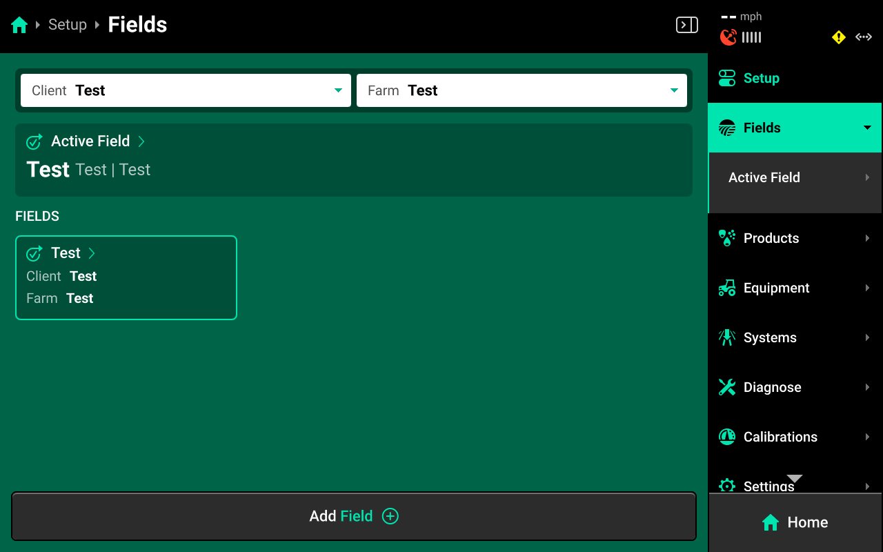
Scroll down on Field Details in the left window and press Crop. Select the desired preset crop in the right window, or press Add Crop + in the bottom right window and use the popup keyboard to enter a custom crop name.
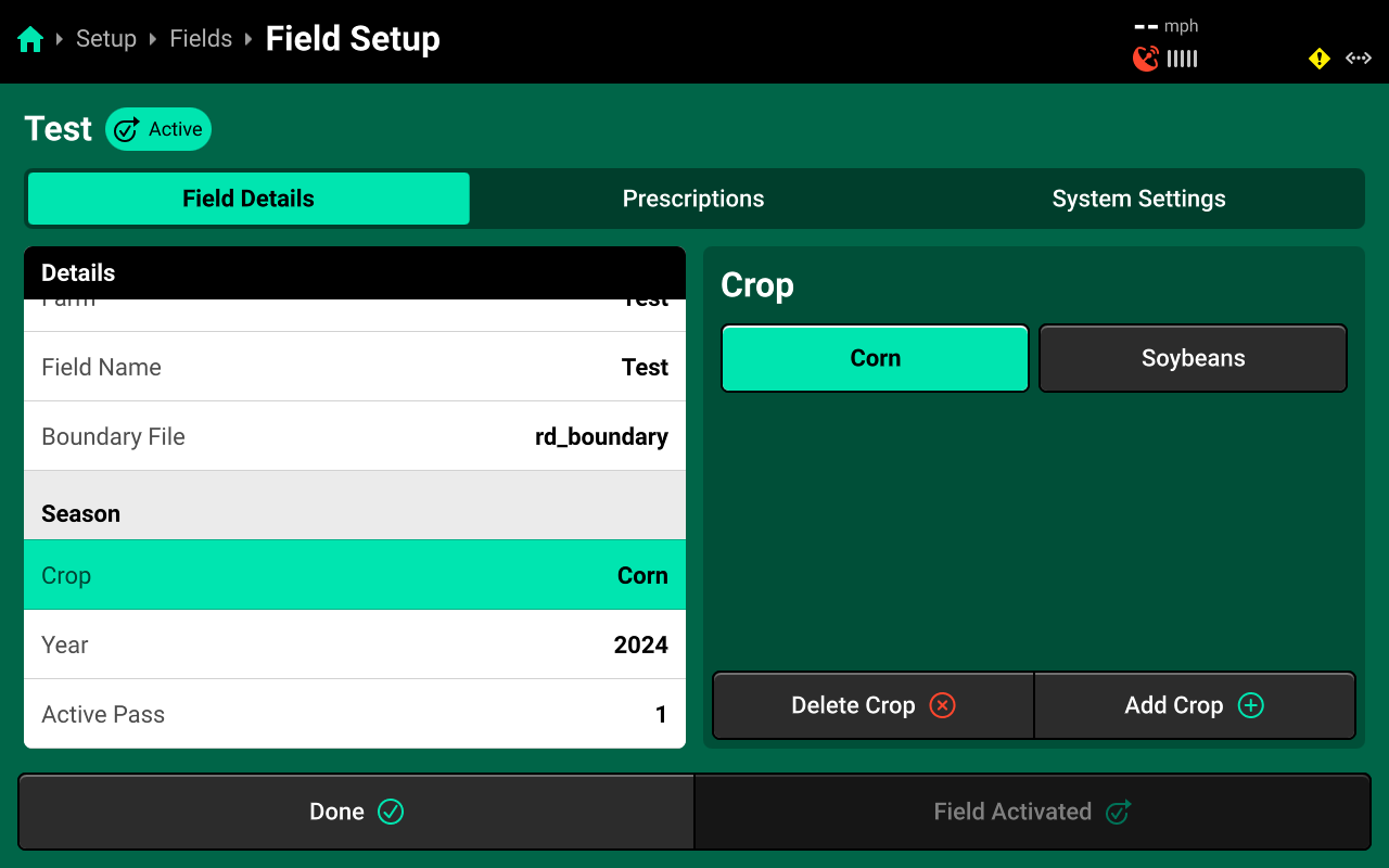
Crop changing will only be available on the active field. If the field is not active, press Make Field Active in the bottom right to display the Crop setting.
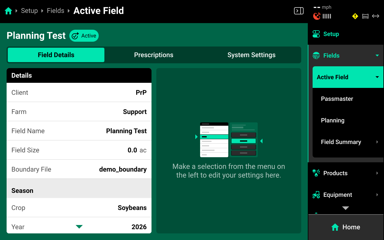
A condensed version of this screen is accessible by navigating to Setup > Fields > Active Field. All Settings may be adjusted from this screen as well.
Crop Settings
Different settings in the menus of the 20|20 are designated as Crop Settings, indicated by the Crop Setting icon ![]() .
.
All Crop Setting changes will be saved to the current active crop. After switching from a new crop back to any other previous crop, all Crop Settings will revert to the last saved value for that crop. Use this feature to streamline the process of changing from one crop to another.
For example, a user may switch the Active Crop from Corn to Soybeans, and then select the correct Seeds / Disk, the correct Active Rows, and different control widget presets for Soybeans. When the user switches the Active Crop back to Corn, the 20|20 will automatically revert those settings back to the last active values for Corn. When the user switches the Active Crop back to Soybeans, the 20|20 will revert those settings again.
All Crop Settings have the same default values. The user must change each of the desired values once with the correct crop active to save those settings to the desired crop.
List of Crop Settings
The following list indicates which settings are saved to the Active Crop.
- Setup > Equipment
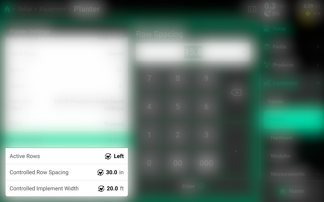
- Active Rows
- Controlled Row Spacing
- Controlled Implement Width (Not typically adjusted manually - the 20|20 computes this value automatically)
- Setup > Systems / Field System Settings
- Default Population / Rate
- Seeds per Disk
- Control Screen
- Population Set Points (Seeding-type system only)
 Prescriptions and Boundaries
Prescriptions and boundaries must be assigned to each field manually. There are two ways to import prescriptions and boundaries to the 20|20:
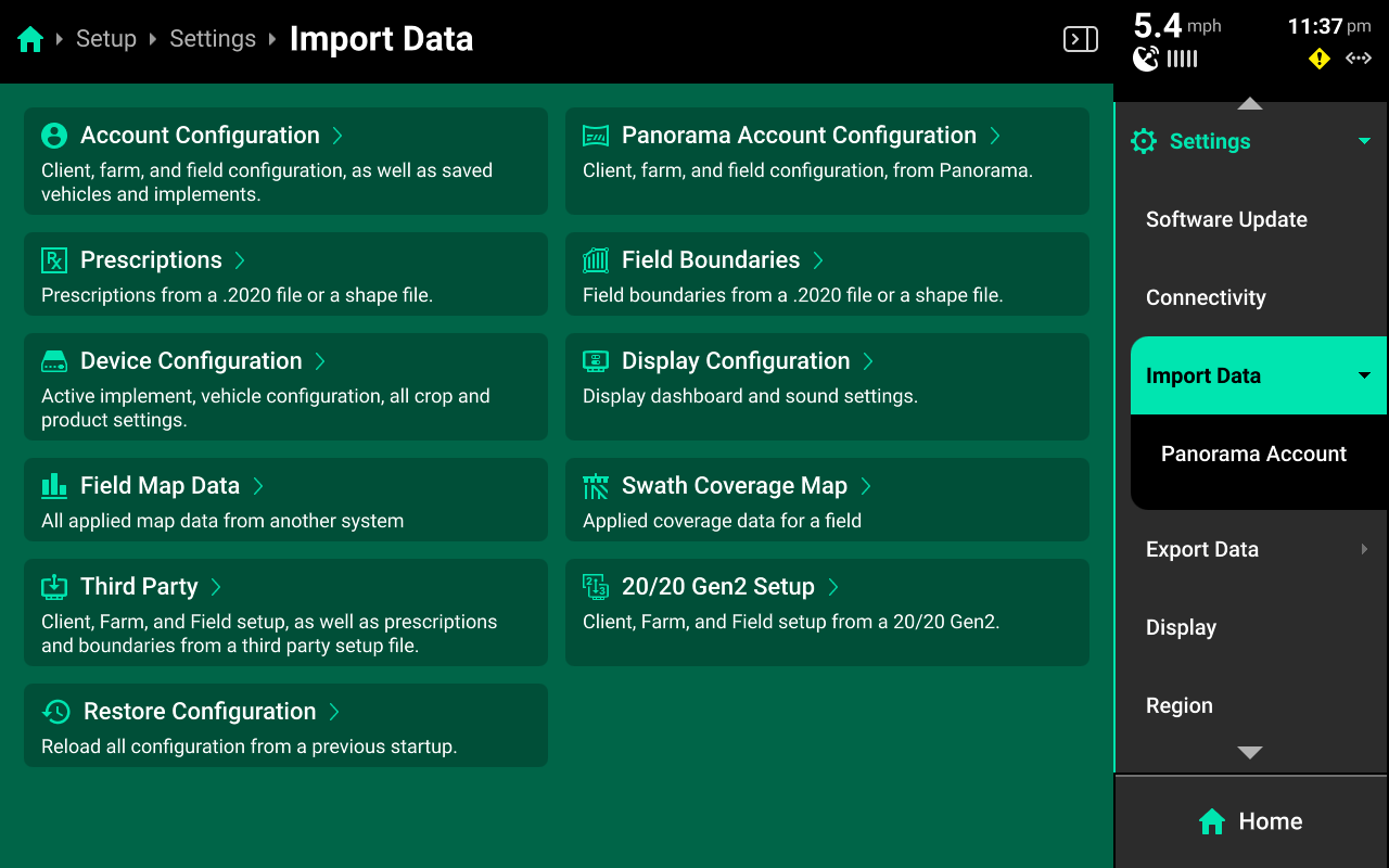
- From an external USB drive into the 20|20 by navigating to Setup > Settings > Import Data and selecting Prescriptions or Field Boundaries. See Import Data in the 20|20 Gen 3 Operator's Guide for more details.
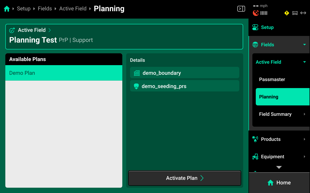
- From a field work plan created in Panorama by Navigating to Setup > Fields > Active Field > Planning and selecting / activating a plan. See Planning in the 20|20 Gen 3 Operator's Guide for more details.
After the files / plans are imported, navigate to Setup > Fields and select the desired field from the table in the center, or select Active Field under Fields in the Navigation Menu.
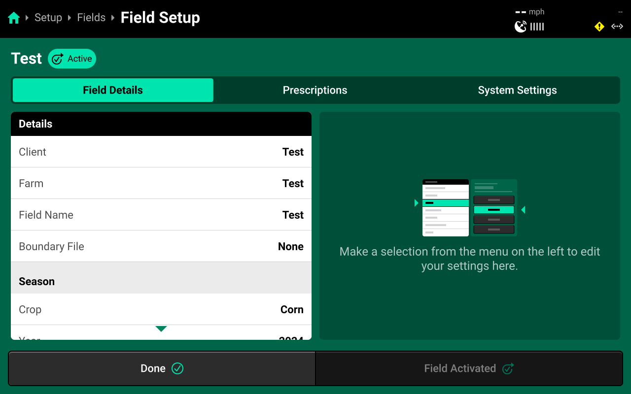
Boundaries
If boundaries were imported through a USB drive, press Field Boundary in the left window and select the desired boundary in the right window to assign that boundary to the field. If boundaries were imported through a Plan, they will already be assigned to the field.
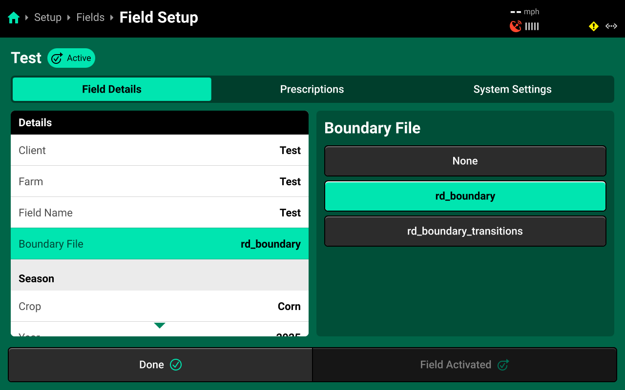
Once assigned, the field boundary will be available as a map layer on the Home Screen.
Prescriptions
Press the Prescriptions tab at the top to assign prescriptions.
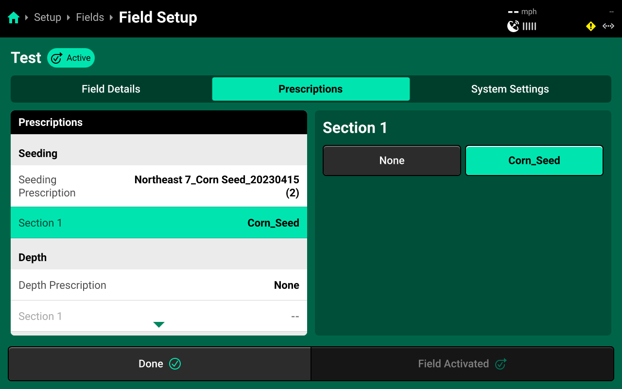
If prescriptions were imported through a USB drive, press Seeding Prescription in the right window and select the desired prescription file from the list in the right window. Then press the desired Rate Section in the left window and select the desired prescription attribute in the right window. If prescriptions were imported through a Plan, they will already be assigned to the field.
An attribute must be assigned to each desired rate section(s) to engage prescription control.
 Using Hybrids
Navigate to Setup > Products and select [Seeding System Name] to add, delete, or modify hybrids.
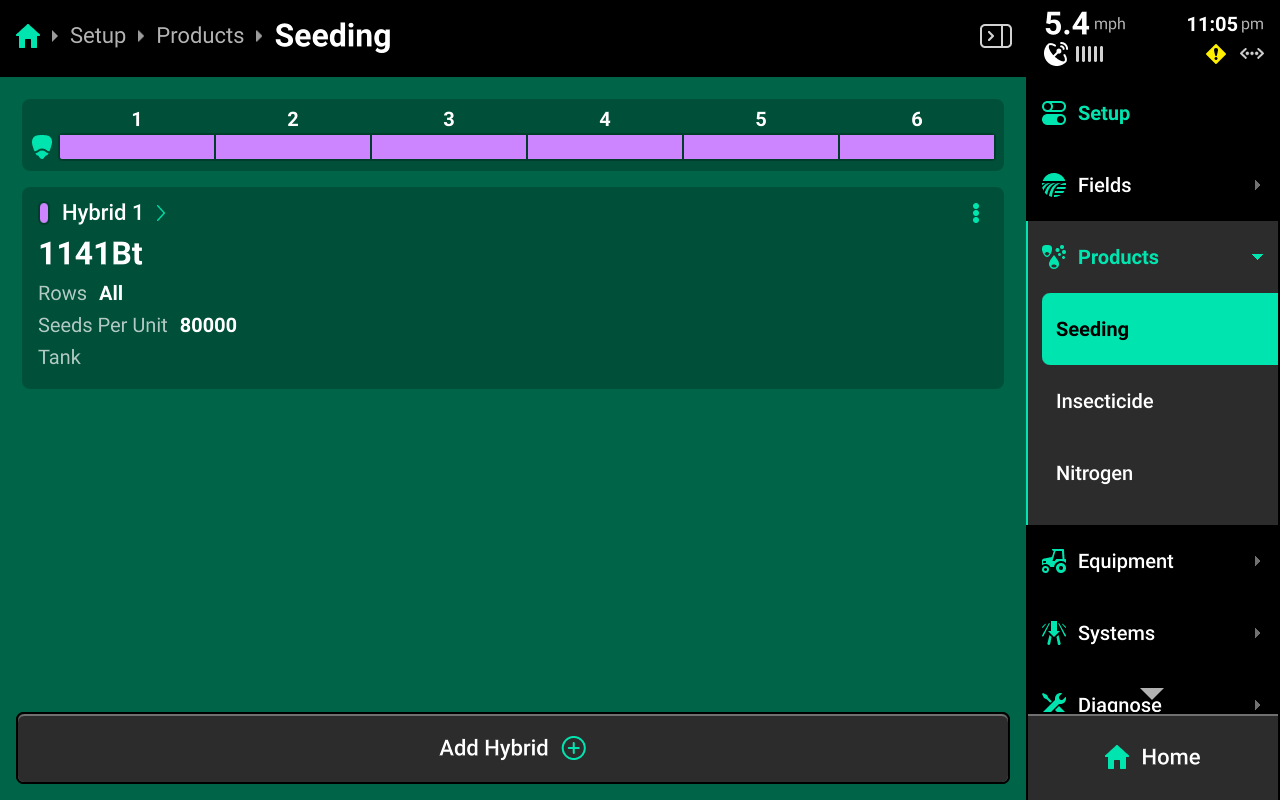
A table of hybrid entries is displayed in the center. Press Add Hybrid + to immediately add a numbered hybrid entry to this table. Press the ![]() Icon next to any entry displayed in the table to delete it.
Icon next to any entry displayed in the table to delete it.
Press on any entry once it has been added to open Hybrid Setup.
Hybrid Setup Screen
Use the Hybrid Setup screen to select or enter a hybrid name, modify hybrid volumetric attributes, or set the active rows for the selected hybrid.
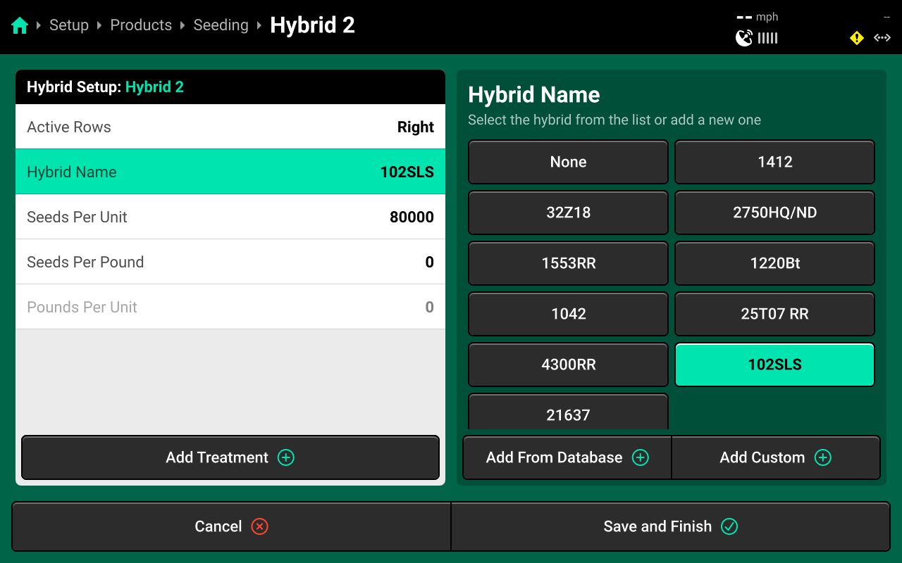
The Hybrid Name list is limited to 10 names. Adding an eleventh name will remove the oldest name from this table, but will not remove any entries from the table on the previous screen.
Precision Planting Product Support recommends using the table of hybrid entries displayed on Setup > Products > [Seeding System Name] as the "master list" of hybrids, rather than the Hybrid Name list on the Hybrid Setup screen. Select a hybrid entry and modify the active rows to "change" hybrids. Adding / deleting hybrids from the list on the Hybrid Setup screen will not remove saved names for the entries. The list of hybrid entries is saved to the Equipment profile. See the Hybrid Setup video in the "Video" section of cloud.precisionplanting.com - Gen 3 25.1.x for more information.
 Calibrations
There are no Calibrations available for sensing-only seeding systems. Monitor the Diagnose charts for the Smart Connector while operating the third party seeding control to test the system for functionality.
 Diagnostics
Diagnose Menu Overview
The Diagnose Menu is used to identify and troubleshoot hardware device failures and configuration issues in the 20|20.
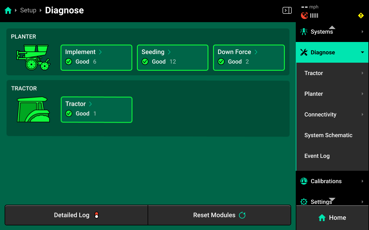
Use the following colors to determine device status on the Diagnose screen.
- Green : Device is working correctly. Communications are good.
- Yellow : Device or sub-component is not 100% functional.
- Red : Device has failed, or is expected and not detected.
- White : Device is detected but not expected.
- Black : Device has been disabled by the user.
- Grey : Device is finishing detecting or unreachable.
- Teal : Device is updating firmware.
Press Reset Modules at the bottom and confirm on the popup to break and reestablish all CAN communication and daisy chain identification. This function is often used as a troubleshooting tool for communication issues.
Due to programming changes for sprayer and seeder compatibility, after pressing Reset Modules or power cycling in software versions 2023.1.0 and above, if a daisy chain break is present in the physical harnessing, all components after the daisy chain break will display red on the diagnose page. The break must be addressed before implement functionality is restored.
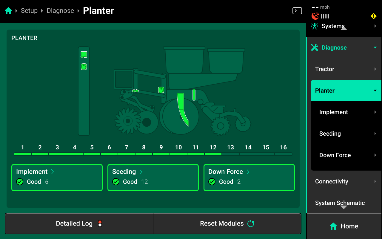
System Diagnostics
To view Smart Connector diagnostics, navigate to Setup > Diagnose, then press anywhere on the Planter or press Planter under Diagnose in the Navigation Menu.
Device Diagnostics
To view Smart Connector device diagnostics, select Implement in the center, or press Implement under Planter in the Navigation Menu, then press SC in the center or in the Navigation Menu.
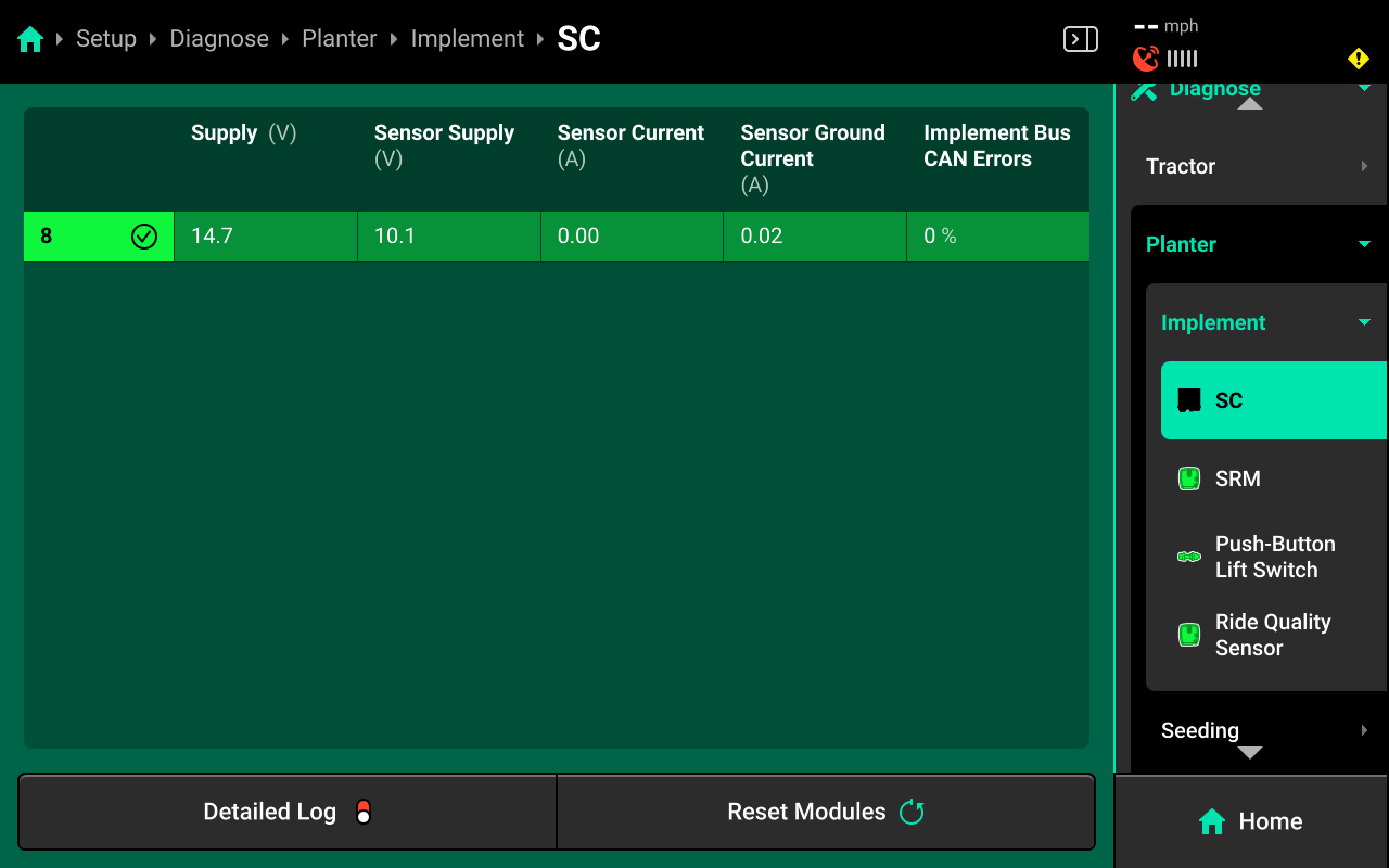
- Supply (V) : Supply voltage to the Smart Connector. Values above 15 or lower than 11.5 indicate an issue with power supply.
- Sensor Supply (V) : Voltage supplied by the Smart Connector to the Seed Sensors. Values lower than 9 will begin to affect population readings.
- Sensor Current (A) : Total amperage supplied to all Seed Sensors.
- Sensor Ground Current (A) : Values greater than 0 may indicate a crossed ground or damaged planter harness.
- Implement Bus CAN Errors : High / climbing errors indicate damage to the Smart Connector or CAN harness between the DBM / Smart Connector.
Signal Diagnostics
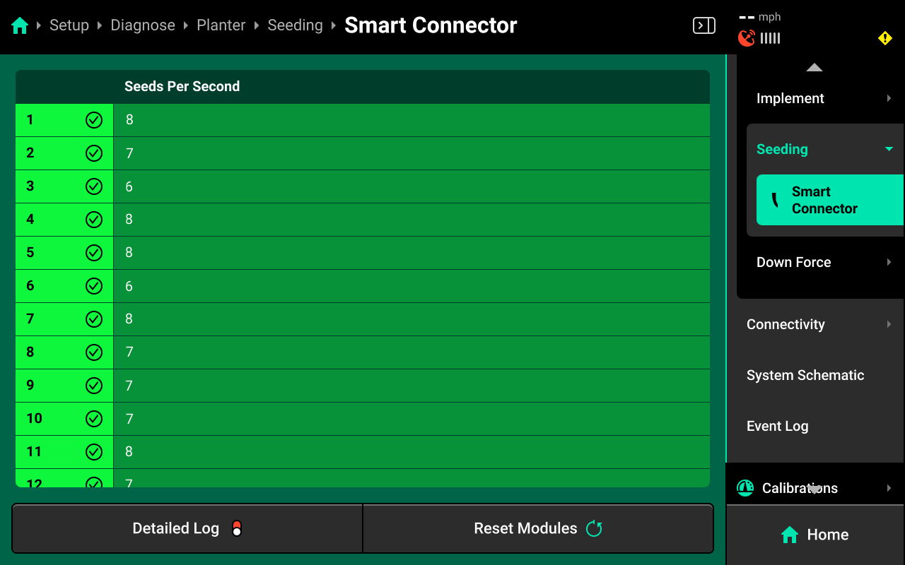
To view Smart Connector signal diagnostics, select [Seeding System Name] in the center or under Planter in the Navigation Menu.
Press Smart Connector in the center or in the Navigation Menu to view Seeds per Second readings received by the Smart Connector from the Seed Sensors.
Common Troubleshooting Issues
Diagnose screen
Verify hardware health using the color key provided at the beginning of this section. Common issues include:
-
Yellow Devices:
- High amp draw may indicate damage to the planter harness / seed sensors.
- Low / High supply voltage may indicate damaged harnessing between the DBM and Smart Connector.
-
Red Devices:
- Damaged Smart Connector and / or CAN harnessing.
- Disconnected hardware.
- Misconfigured system setup.
-
White Devices:
- Incomplete system setup.
- Contradictory CAN Module / Hardware setup.
Physical Diagnostics
Each Smart Connector has a red LED on the module which will blink with a pattern that indicates module health / status. When troubleshooting, inspect the physical module to quickly identify possible issues using the LED.
| Light Pattern | Indicated Status |
|---|---|
| No Light | Device Unpowered |
| Solid Light | Updating Device Firmware |
| 5hz Blink | Device Powered, Event Code Active |
| 1hz Blink | Device Healthy |
| Erratic Blink | Device Powered, No CAN Communication |