YieldSense Operator’s Guide
Contents
- YieldSense Requirements
- Major Changes
- Home Screen
- Equipment Setup
- System Setup
- Crop Calibration
- System Calibrations
- Diagnostics
- YieldSight Installation
This guide is intended for use with limited release software 2025.1.0 and its variants. Due to the nature of the limited release software update process, screenshots and descriptions provided in this guide may differ from the current version. Updates are made to this guide as often as possible. To download the most recent version of Gen 3 software, visit 2020.ag
YieldSense Requirements
- 2025.1.7 or later software installed.
- YieldSense system configured on the 20|20.
- Speed source active.
- CCM master plant switch in the up position if CCM is installed.
- Combine Head must read lowered.
Major Changes / FAQ
2025.1.x software introduces many changes to system organization. Major changes, frequently asked questions, and known issues related to the YieldSense system are detailed here.
Software Compatibility
2025.1.7 or the most current version of software is the only functional 2025.1 software version for combines. All users on software versions older than 2025.1.7 will be required to update to current software before troubleshooting will be provided by Precision Planting Product Support.
YieldSense / YieldSight
Precision planting now offers a harvest option which reads flow sensor data from an OEM CAN Flow Sensor (YieldSight) in addition to full Flow Sensor / Elevator Chain replacement (YieldSense). System operation for both systems is the same. There are minor software setup differences which are covered in this guide. Hardware installation for YieldSight is covered in the final section of this guide.
YieldSense Calibration
Crop Constant calibration is no longer performed on the Home Screen after changing crop as in previous versions of Gen 3 20|20 software. To calibrate the Crop Constant, harvest an initial load of at least 25,000 lbs and start a new load. After acquiring a scale ticket for the initial load from a certified scale, access the Load List using the Load List Widget.
Grain carts are not an acceptable substitute for a certified scale.
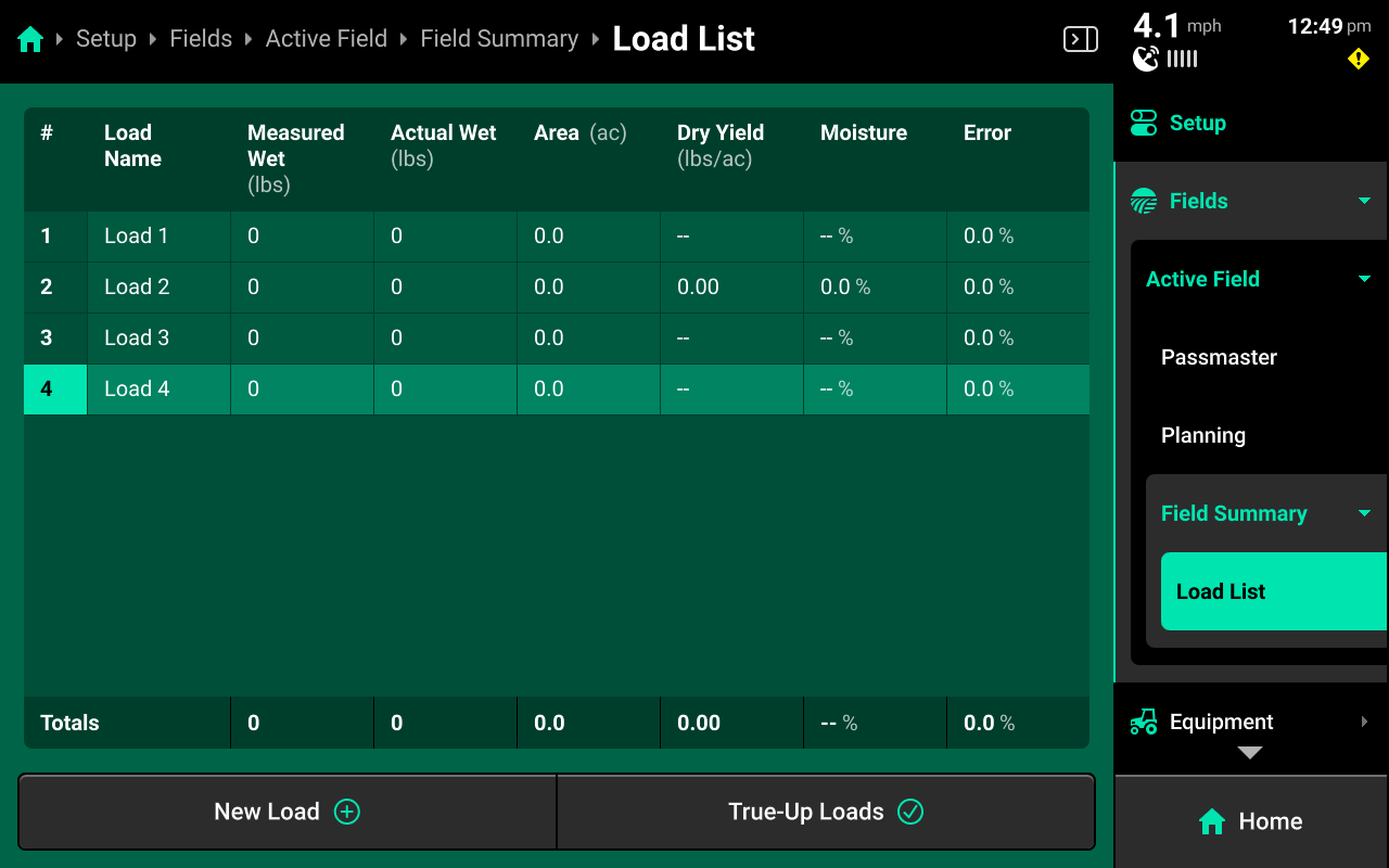
During operation, the values in the load list tables will be populated with numerical values. The above screenshot is intended for illustration purposes only.
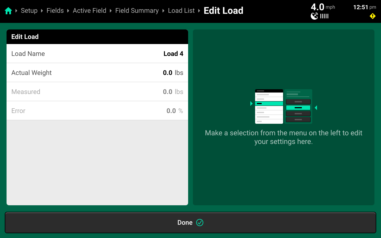
Select the initial load to open the Edit Load screen. Enter the value from the scale ticket in the Actual Weight line, then press Done at the bottom to return to the load list. Press True-up Loads at the bottom to apply the calibrated value to each load in the Active Field, and to all following loads in any field.
If multiple actual weights are entered, the 20|20 will calculate the new constant based on an average of all differences.
To apply a trued-up constant to a field that was harvested prior to calibration, make the desired field active. This will apply the calibrated value to all loads in the current Active Field.
Making Previous Fields Active
As of 2025.1.7, making a previous field active after trueing-up in another field will automatically apply the new crop constant to all weights in the current active field. Do not make a field active unless wishing to apply the current crop constant to that field.
Passmaster Data Sharing
For operations with multiple combines, data sharing between multiple Gen 3 20|20s may be utilized with the Passmaster feature. To set up Passmaster data sharing, see Passmaster Setup and Passmaster Diagnostics in the Gen 3 20|20 Operator's Guide.
The Passmaster feature is data-intensive. Smart phone and tablet hotspots are designed for short-term download usage and do not have the long-term connectivity and upload speed capabilities necessary for Passmaster data sharing. Precision Planting Product Support strongly recommends using a third-party dedicated router for Passmaster data sharing. Troubleshooting for smart phone and tablet hotspot connection issues will be limited to restarting and reconnecting to the hotspot.
Saving Crop Constants
Unique Crop Constants for each crop are saved to each individual Combine Head profile. Each profile starts with all constants at the default value of 1.0. After selecting a crop on the field setup screen and trueing up a load, ensure to update the active Combine Head profile to save the calibrated constant. Repeat this process for each Combine Head / Crop combination after trueing-up.
To avoid using multiple Combine Head profiles, each time the user switches from a Row Head to Platform Head or vice versa, it will be necessary to Navigate to Setup > Equipment > Combine and change the Frame (Head) Type and number of Rows, in addition to modifying all appropriate measurements under Setup > Equipment > Combine > Measurements.
To reset the crop constant, navigate to Setup > Systems > Harvest and open the [Crop Name] Calibrations tab at the top of the screen.
See the following sections of this guide and the 2025.1.x Gen 3 20|20 Operator's Guide for more information on general navigation, switching head types and using widgets on the home screen.
Changing Crop
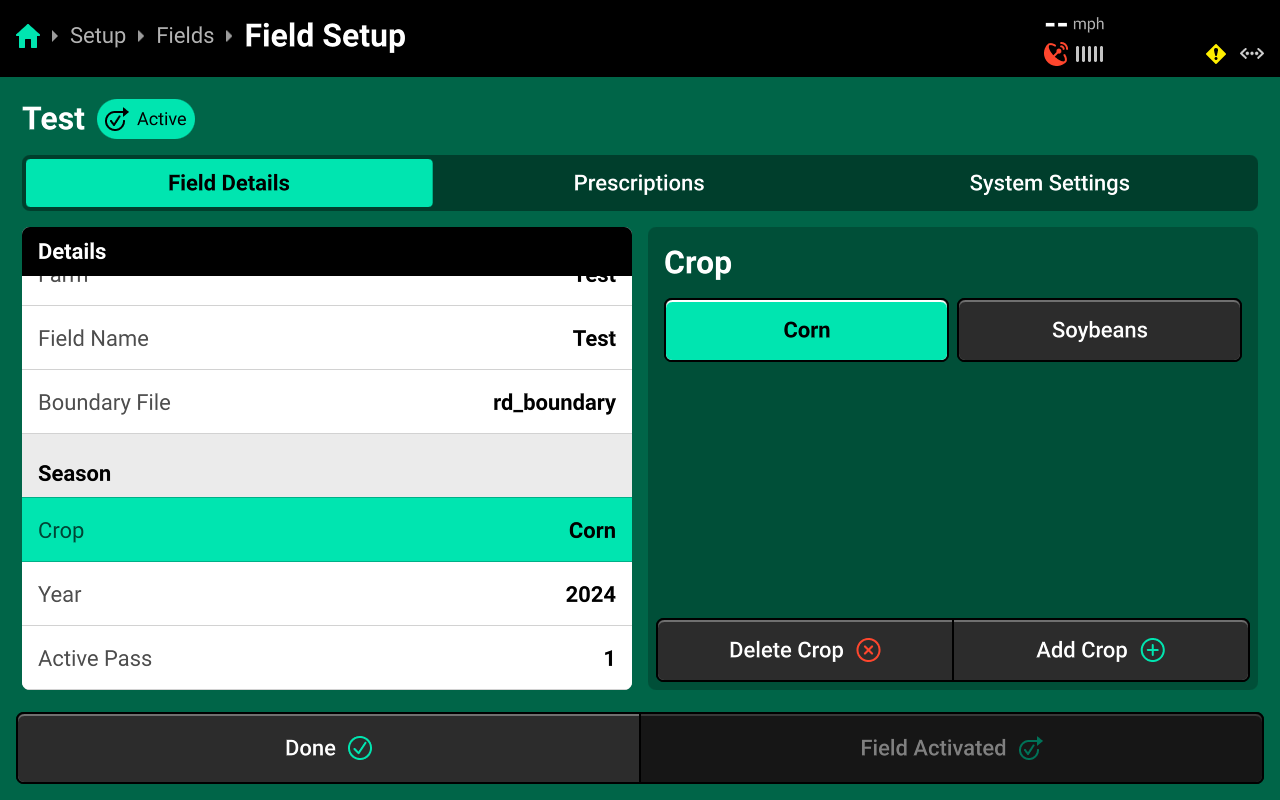
To select the correct Crop, navigate to Setup > Fields then select the desired field from the table in the center, or press Active Field under Fields in the Navigation Menu.
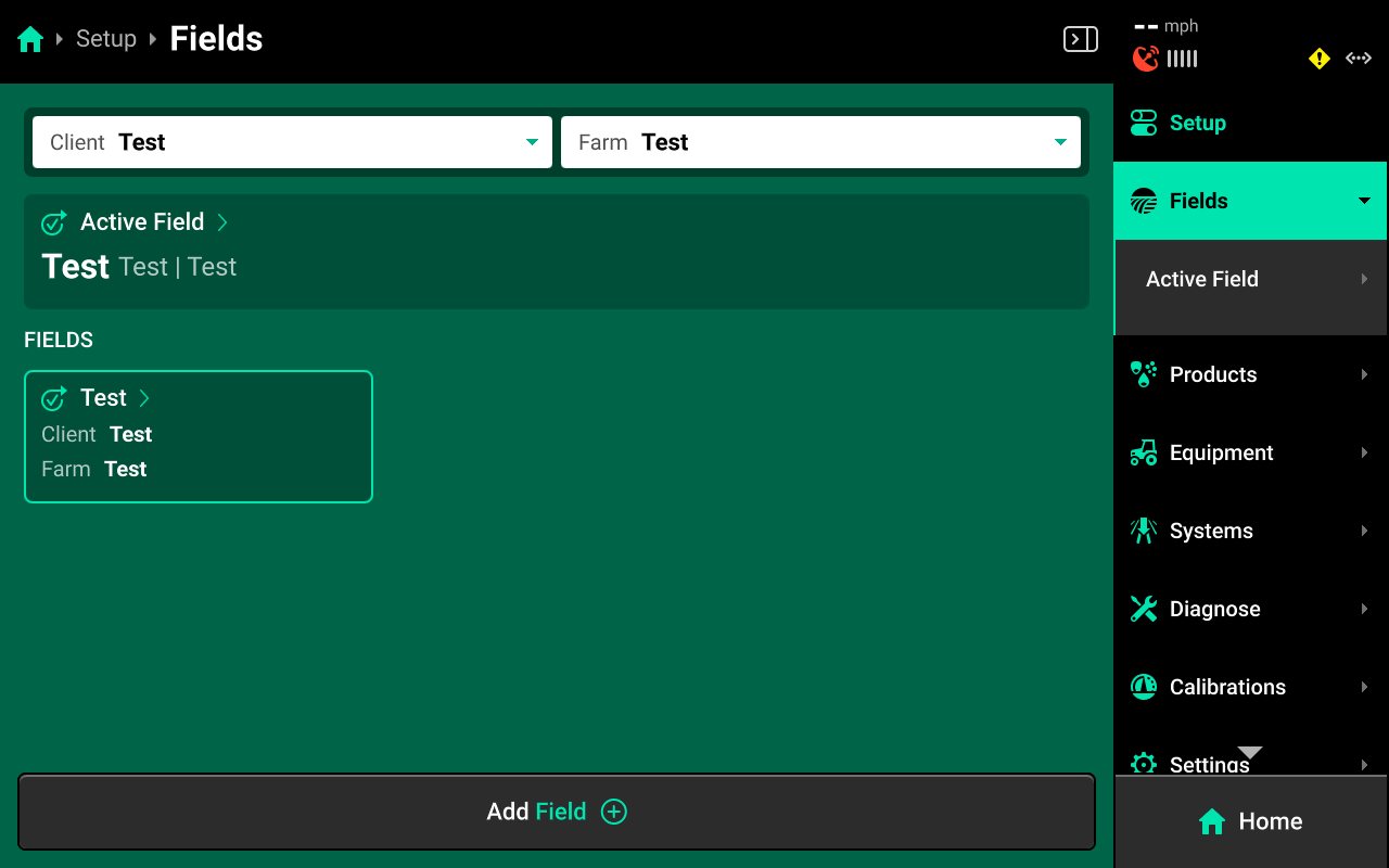
Scroll down on Field Details in the left window and press Crop. Select the desired preset crop in the right window, or press Add Crop + in the bottom right window and use the popup keyboard to enter a custom crop name.
The Crop setting will only be available on the active field. If the field is not active, press Make Field Active in the bottom right to adjust the Crop setting.
This setting only changes what crop the 20|20 will classify the current harvest data under. Changing crop does not change combine head or any other settings except for the active crop constant.
Work State Readings
The Work State Widget will not accurately display combine work state unless the Separator is engaged. To view work state before harvest season, use the Head Height Sensor Diagnose screen, or engage the separator to read the values from the Home Screen.
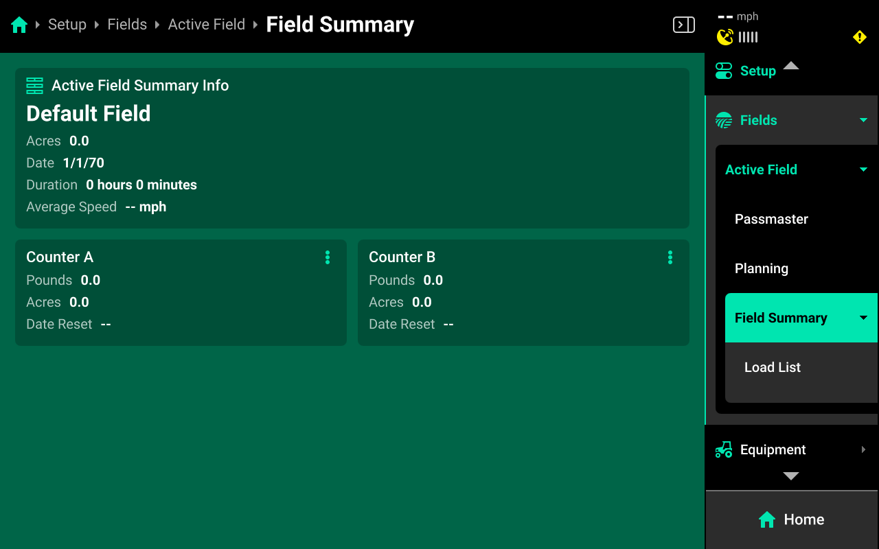
Acre Counters
As of 25.1.7, the ability to reset the acre counters is not available from the home screen widgets. To reset the acre counters, navigate to Setup > Fields > Active Field > Field Summary. Press the three dots on Counter A or B and press Reset.
DBM Storage
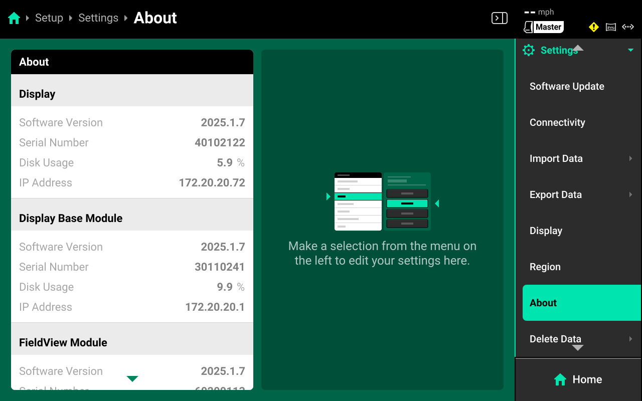
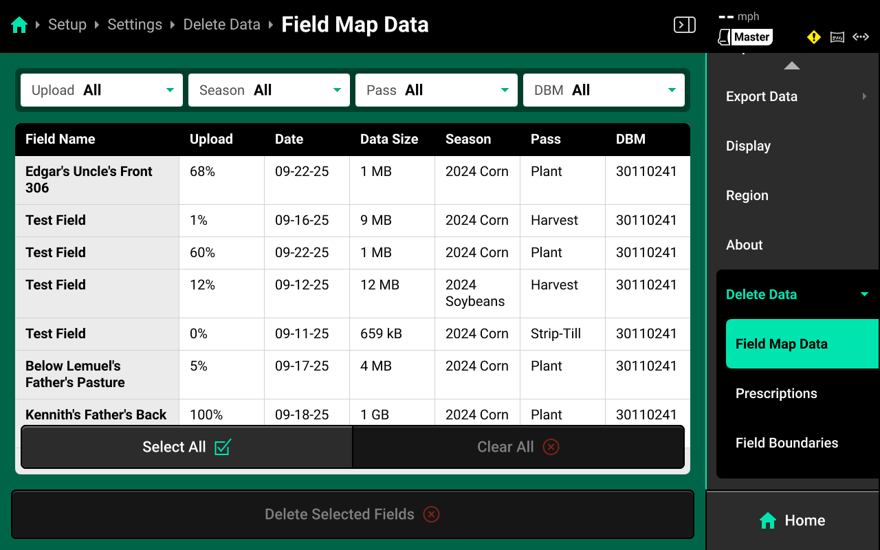
If experiencing issues with maps not building or widgets not displaying values, ensure to check DBM disk usage. Navigate to Setup > Settings > About to view Display Base Module disk usage. Usage of >70% may cause performance issues. If usage exceeds 70%, back up field data to an external source, then delete data from the Gen 3 using the menu located at Setup > Settings > Delete Data > Field Map Data. See the 2025.1.x Gen 3 20|20 Operator's Guide for more information on using the Delete Data menu.
After Navigating to Setup > Settings > About, it may take 5-10 seconds for the system to display disk usage %. If usage reads 0.0%, wait until a non-zero number loads.
Updating From Older Software
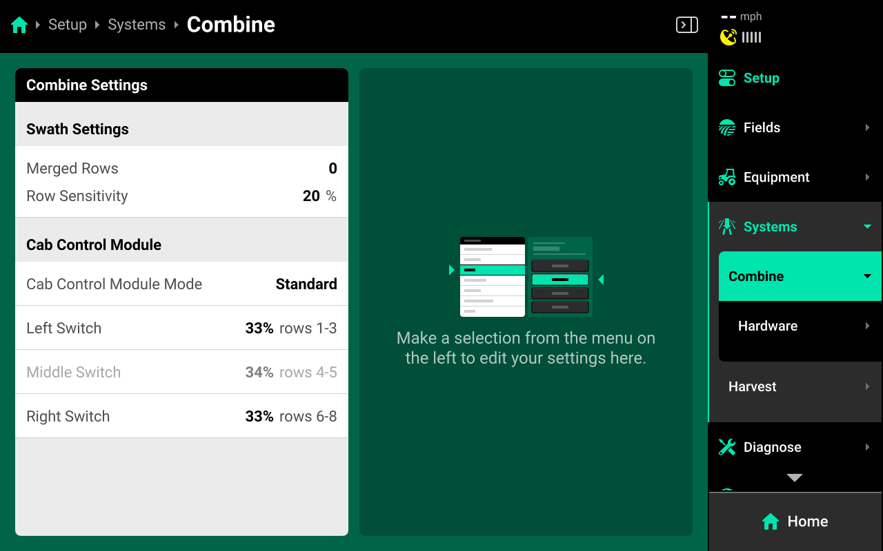
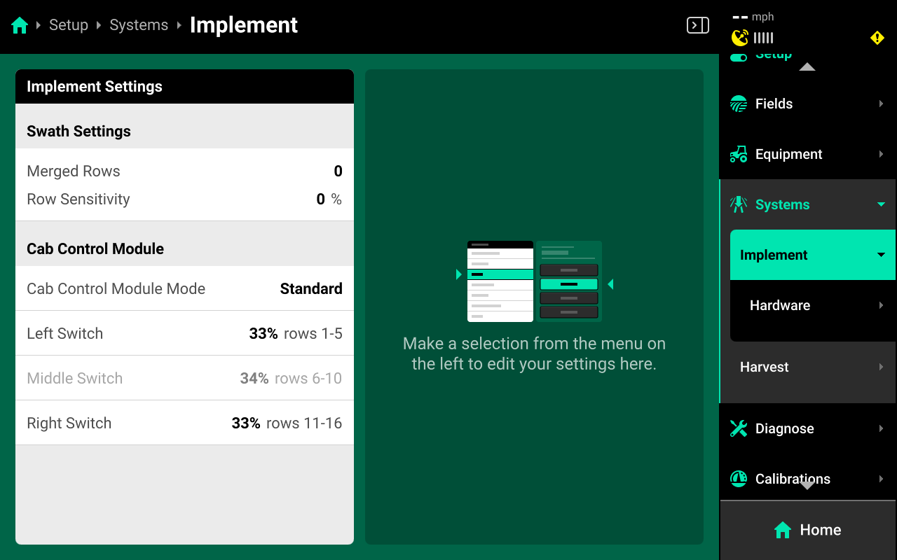
Config Forwarding
Due to a config forwarding issue, the default system located at Setup > Systems may read "Implement" instead of "Combine" after updating from an older version of software to 25.1.x. This may result in incorrect system function. To correct this issue, save the active Combine Cab profile and delete the existing Combine (Head) profile. Then switch the 20|20 to Planter Mode, and back to Combine Mode. Load the saved Combine Cab profile and create a new Combine (Head) profile. This issue will be corrected in a future software update. Continue reading this guide or see the 2025.1.x Gen 3 20|20 Operator's Guide for more information on saving and loading different profiles and setting up a Combine Head.
Correct System Name
Incorrect System Name
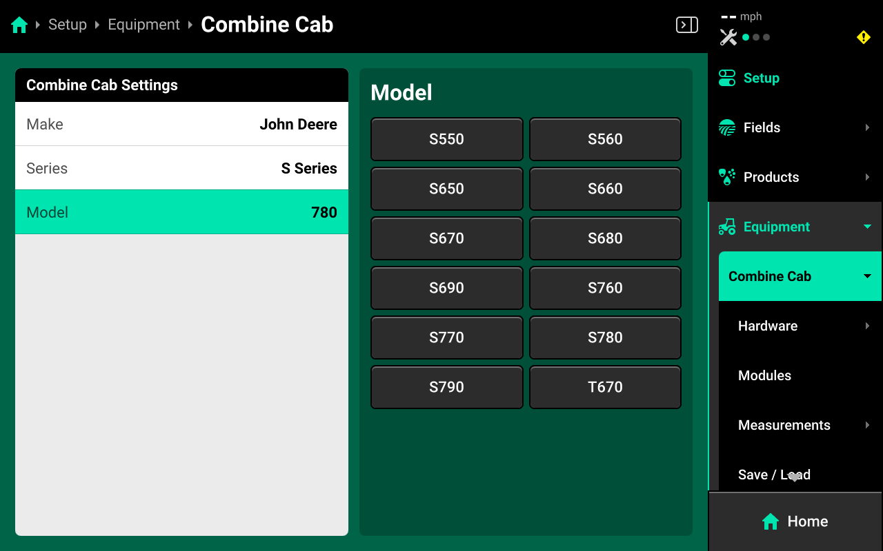
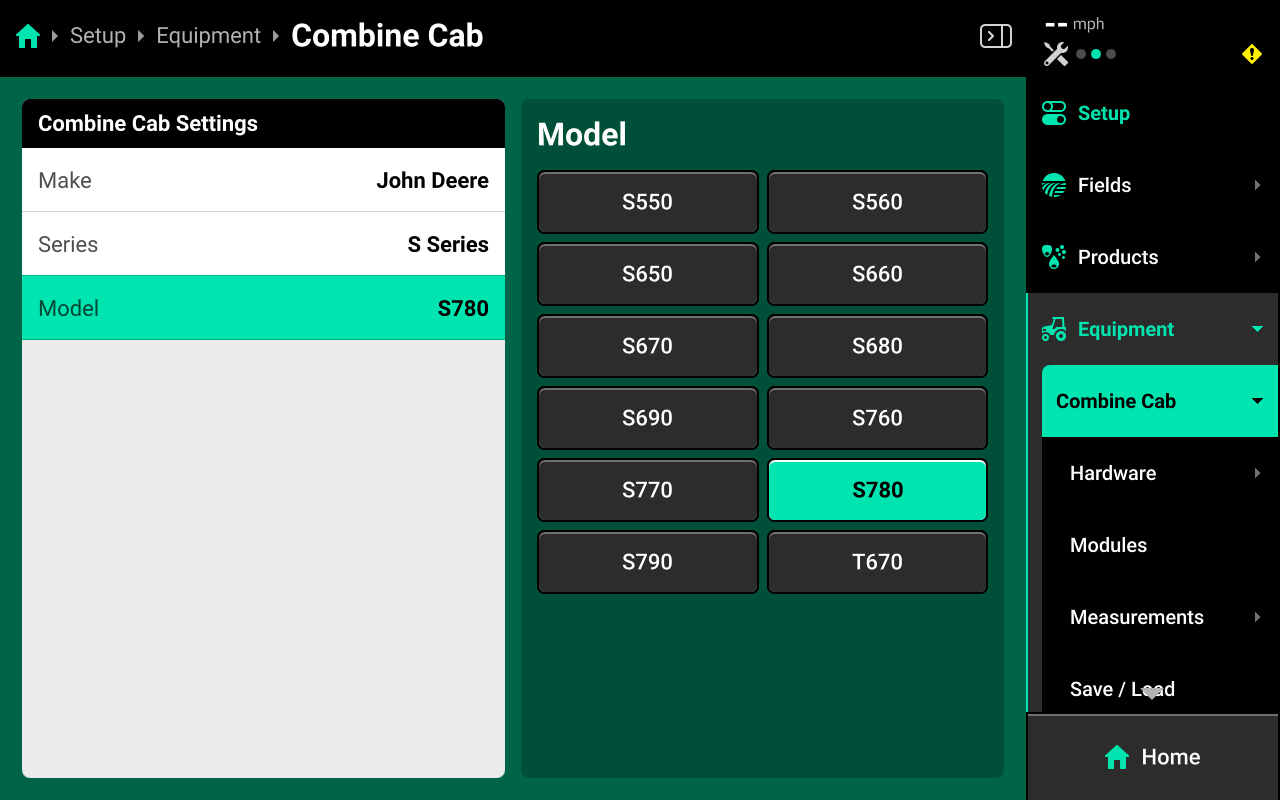
Combine Model Forwarding
After updating from older versions of software, certain models of combine may have the incorrect name (e.g. "780" as opposed to "S780"). This will cause OEM CAN sensors not to function. To correct this issue, navigate to Setup > Equipment > Combine Cab, select Combine Model in the left window, and press the appropriate name in the table displayed in the right window to update the model name. If the correct Model name is not in the table, change Make / Series type until the correct name is displayed. Ensure to save the Combine Cab profile after updating the name.
Incorrect Model
Correct Model
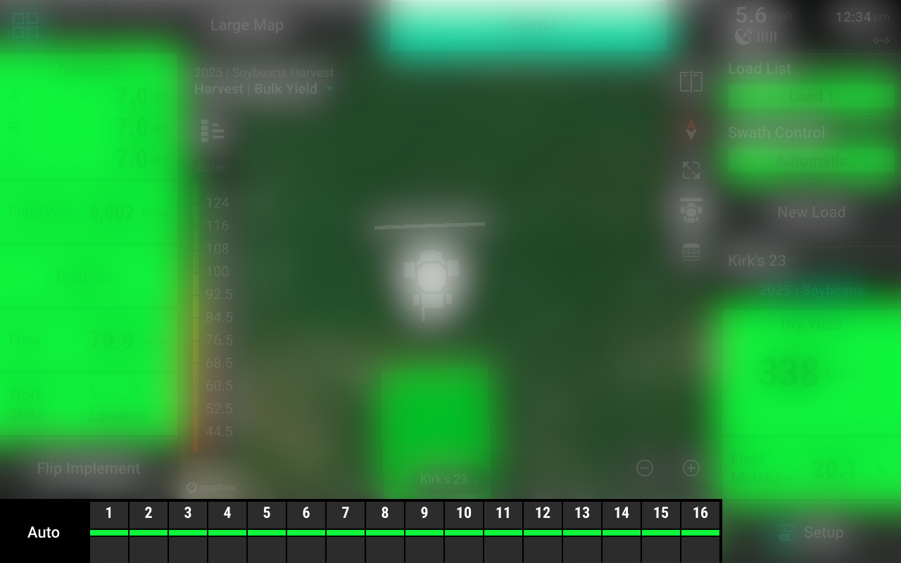
Home Screen
The home screen displays information for mapping the YieldSense system.
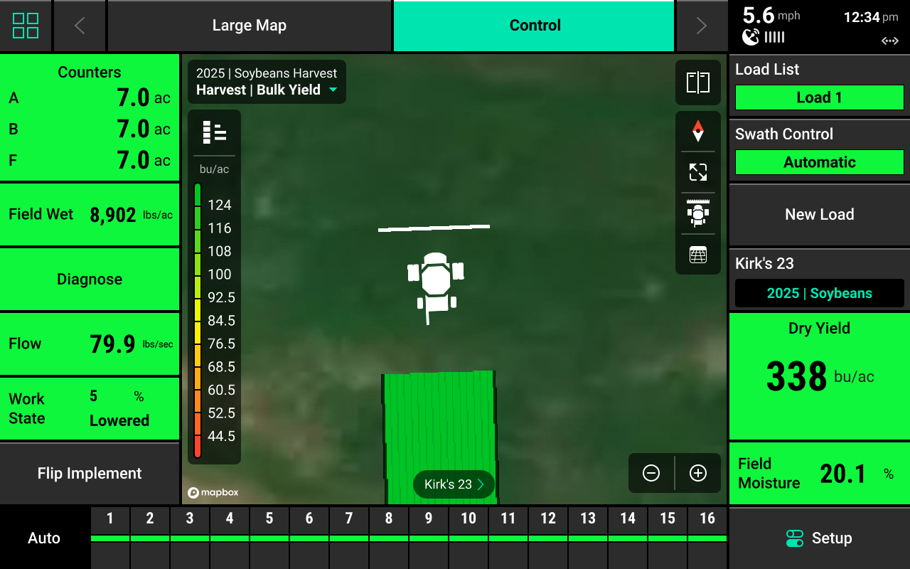
YieldSense Mapping
Different maps are available for the YieldSense system. To view the map layer options, press the current layer name that is displayed in the top left corner of the map. A list of all available maps will be displayed.
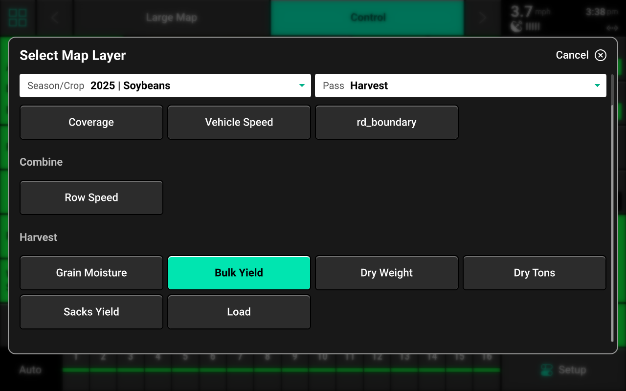
- Coverage : Displays harvest map coverage.
- Remote Coverage : Displays harvest map coverage from other Gen 3 20|20s connected using the PassMaster feature.
- Vehicle Speed / Row Speed : Displays either entire vehicle or individual row speed.
- Bulk Yield / Dry Weight / Dry Tons / Sacks Yield : Each of these map layers display Instant Yield in either Volumetric or Weight-based form.
- Load : Displays areas of the field categorized by load number.
If a field boundary is assigned to the active field, the boundary file will be available as a map layer.
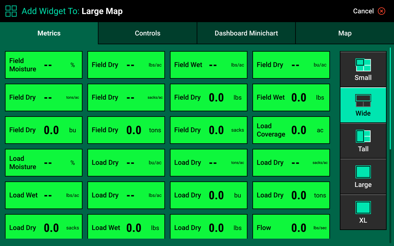
YieldSense Widgets
Press the Four Squares in the top left, then press Add Widget + in the bottom right to view available widgets and add them to the home screen. Different Metrics and Controls may be added to the home screen to control the system or display at-a-glance values for the desired metrics.
Metrics
Controls
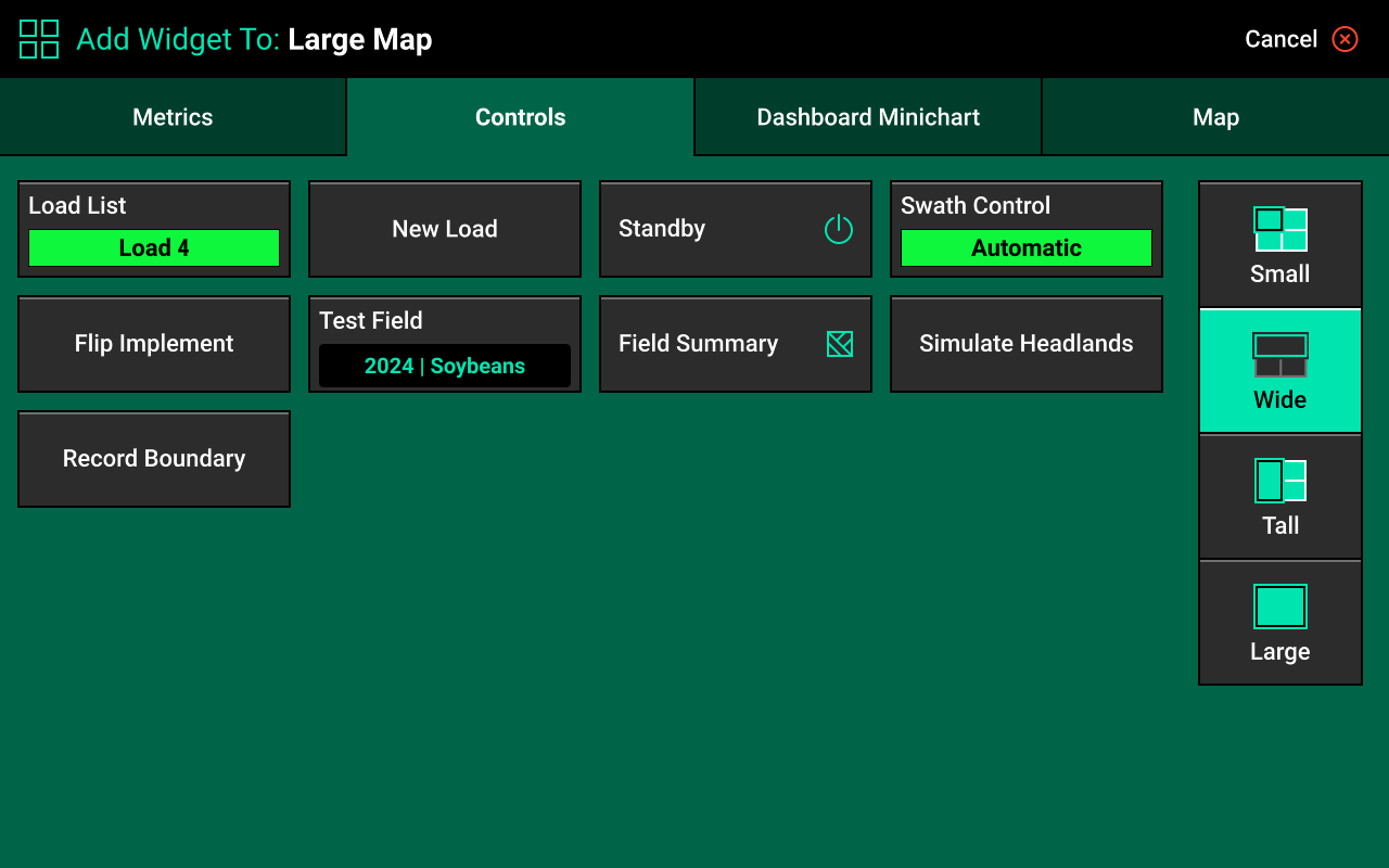
Load List
Use this widget to access the Load List Screen. This is required to perform YieldSense calibration. A new load may also be started from the Load List Screen.
New Load
Use this widget to start a new load directly from the Home Screen
Swath Control
Use this widget to access the Swath Control Screen to manually swath rows on and off. Any row that is swathed off will not count acres or be used in yield calculations. A Swath Control Bar may also be added to swath rows on / off manually from the Home Screen.
Swath Control Screen
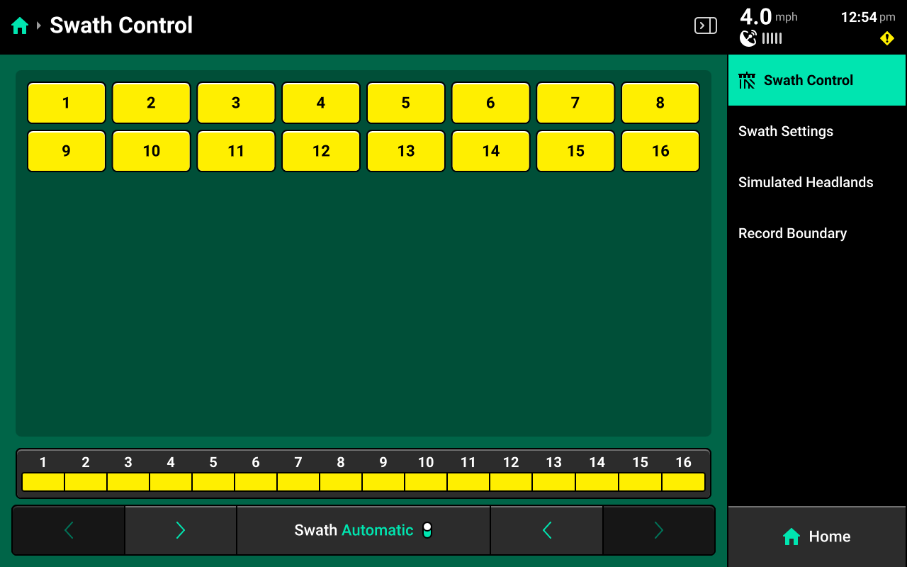
The Swath Control Screen allows the user to manually swath rows on / off, configure a swath control plan, record a boundary, or simulate headlands. Use the table of rows off manually, or use the Swath Control Bar at the bottom using the procedure described in the previous section. Rows that are swathed off will be displayed in yellow.
Swath Settings
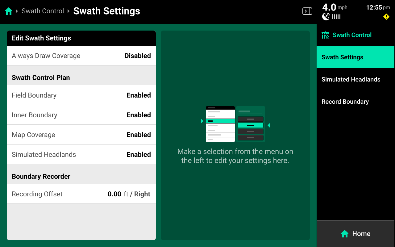
Use these settings to determine how the 20|20 draws coverage, to change which parameters the 20|20 will use to swath on / off, or to enter an offset to use when recording boundaries.
The 20|20 will not swath off to any option under Swath Control Plan which is set to Disabled.
Setting Always Draw Coverage to Enabled will cause the 20|20 to draw coverage whether the implement is actively harvesting or not.
Simulated Headlands
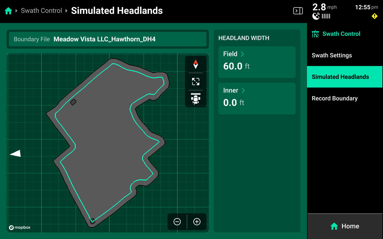
Select a width for Field (Exterior) or Inner to set the simulated headland width for either option.
A Boundary file must be assigned to the field to enable simulated headlands.
Recording Boundaries
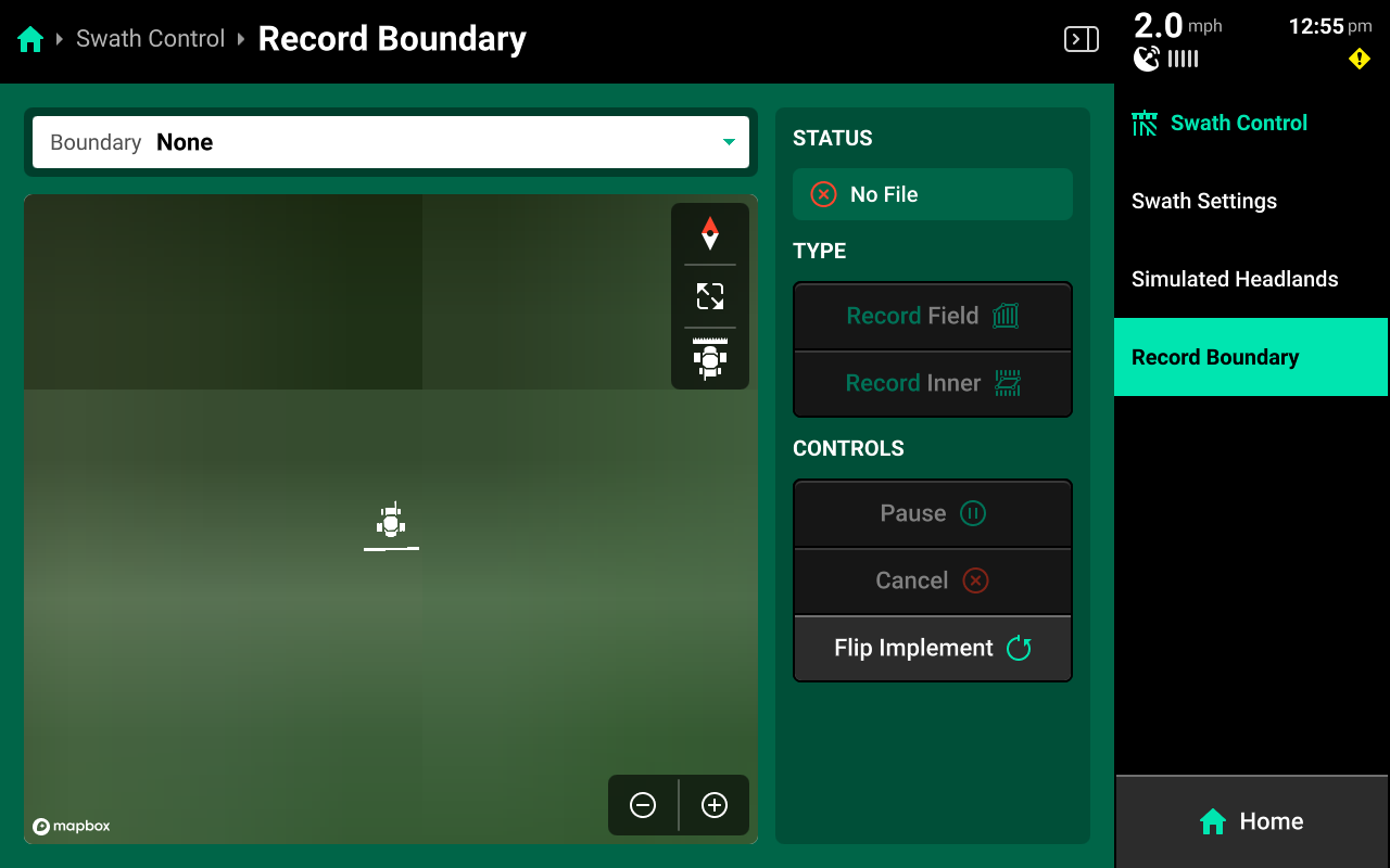
Use the Record Boundary Screen and follow the process detailed below to record a boundary using the 20|20.
- Use the dropdown menu to select an existing boundary to rewrite, or create a new file name.
- Press Record Field (Exterior) or Record Inner to begin recording either type of boundary.
- Use Pause or Cancel to temporarily or permanently stop recording the current boundary. Use Resume to unpause.
- Use Change Direction to correct the tractor heading, if necessary.
- Press Save to keep the current recording.
To ensure maximum accuracy around outer field corners, press Pause after reaching an outer corner. Complete the turn, then back fully into the corner. Press Resume when the tractor is properly repositioned.
Swath Control Bar
When added to the Home Screen, the Swath Control Bar is displayed at the bottom of the screen. Press any row in the bar to swath that row off and engage Manual Swath Mode.
In Manual Swath Mode, the 20|20 will no longer swath off to boundaries or coverage. To return to Automatic Swath Mode, press Swath Manual in the bottom center.
Equipment Setup
Navigate to Setup > Equipment to begin setting up the Combine. If the 20|20 is not in Combine Mode, save all active equipment profiles, then press Switch Implement Type at the bottom and select Combine.
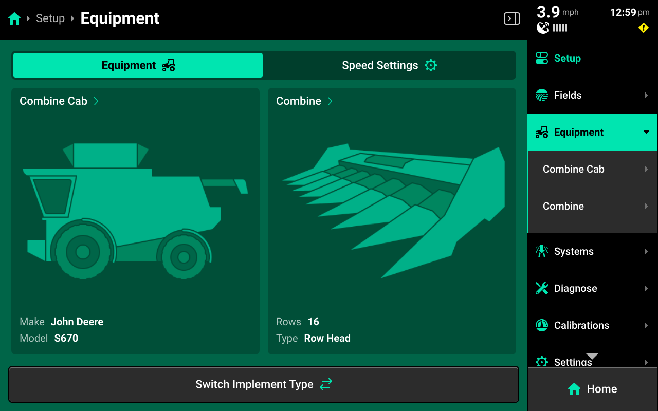
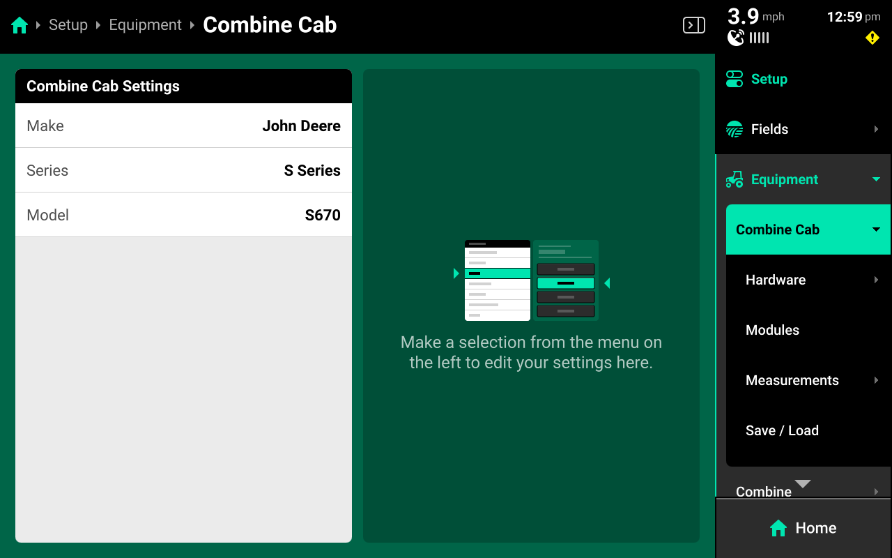
Combine Cab
Navigate to Setup > Equipment > Combine Cab to configure the Combine make / model.
Cab Hardware
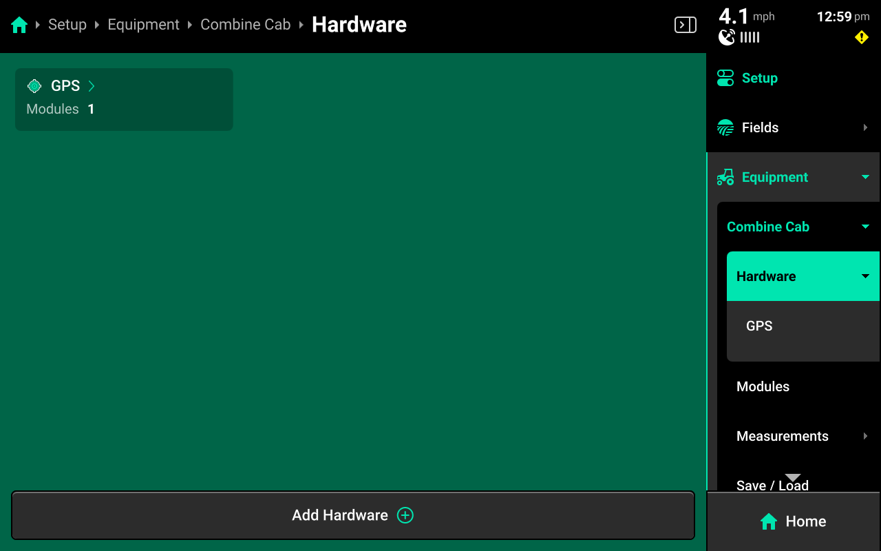
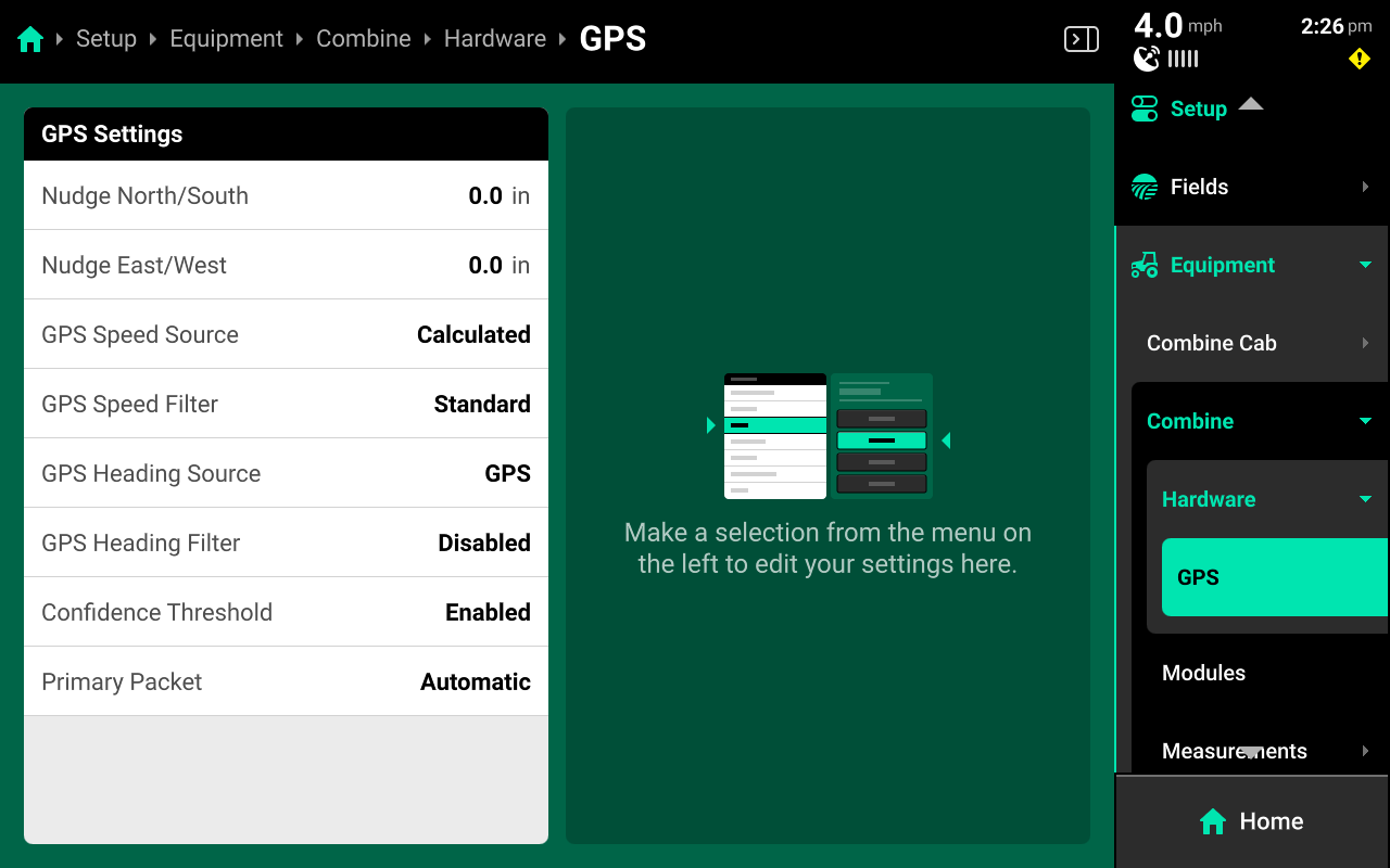
GPS
GPS is configured by default on the combine cab.
Press on GPS under Hardware to access advanced GPS settings. Use the options to nudge GPS signal if necessary. Use the advanced options on this page only if advised by Precision Planting Product Support.
Radar
Radar may be added to the Combine Cab if it is installed. This is not typical for combines. If added, the radar module must be calibrated to function. See the 2025.1.x Gen 3 20|20 Operator's Guide for more information on configuring and calibrating radar.
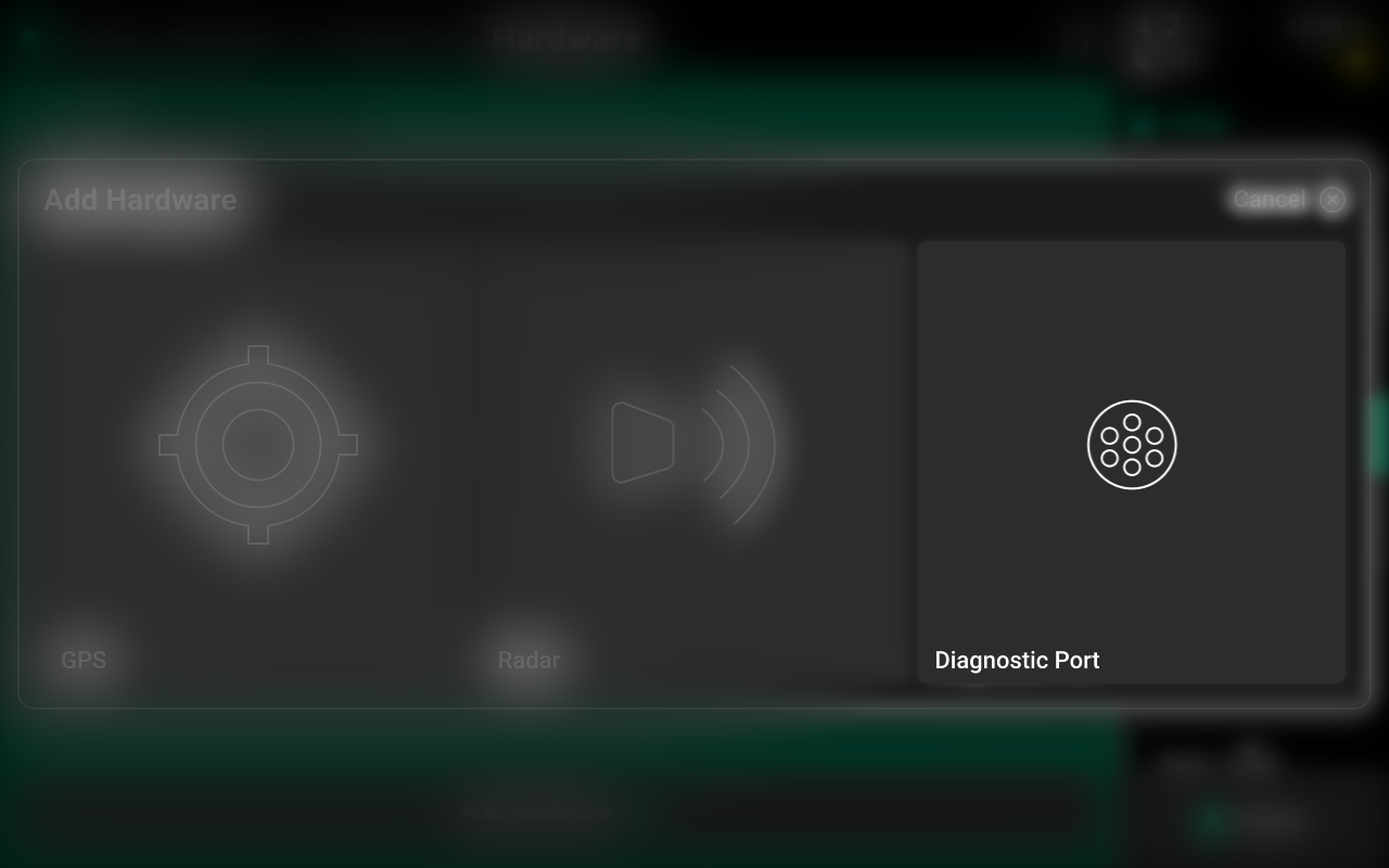
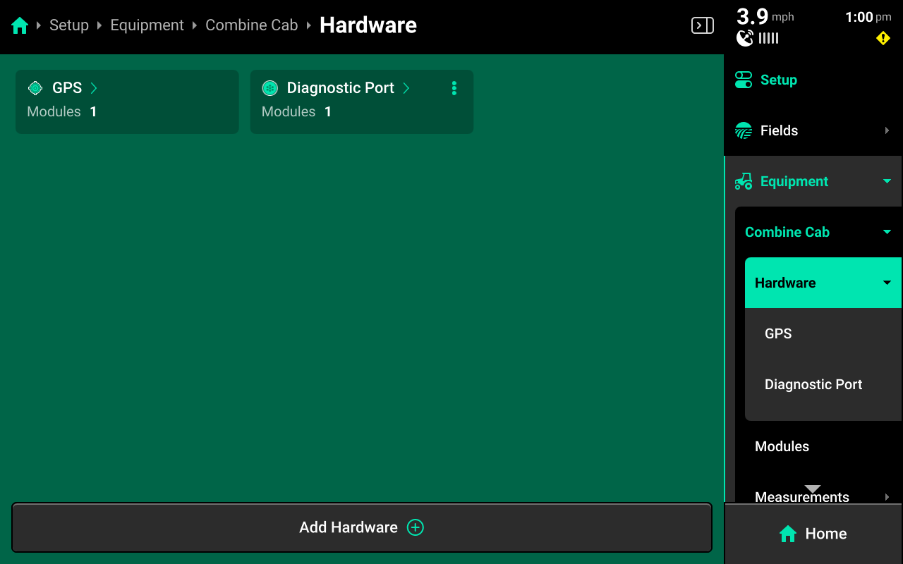
Diagnostic Port
If connecting to OEM CAN on the combine, configure the diagnostic port to receive information on engine load and fuel level.
Press Add Hardware+ and select Diagnostic Port from the popup. Select Frame for the module location and press Save and Finish to exit setup.
The Diagnostic Port will be displayed in white on the Diagnose screen until it is configured on any combine where the Gen 3 20|20 is connected to OEM CAN.
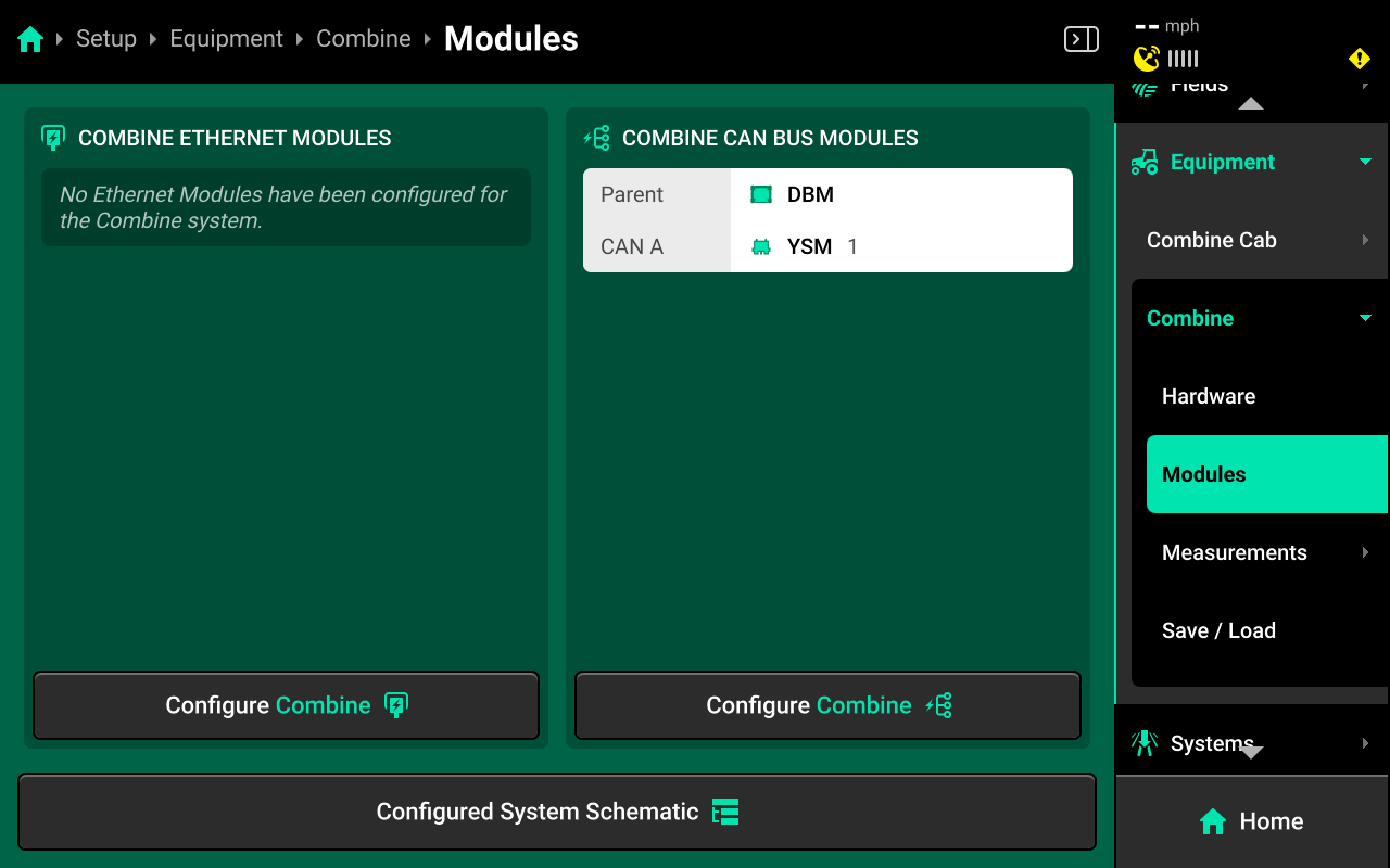
Ethernet Modules
Navigate to Setup > Equipment > Combine Cab > Modules to set up Ethernet modules.
Configure all ethernet modules (Displays, FVM, etc.) on the Combine Cab using the following process.
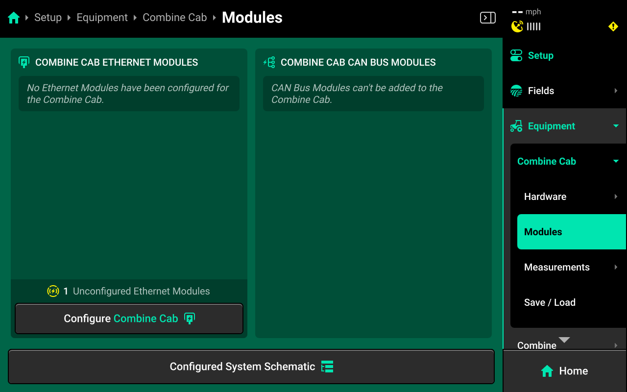
Press Configure Combine Cab in the Combine Cab Ethernet Modules window in the left center screen.
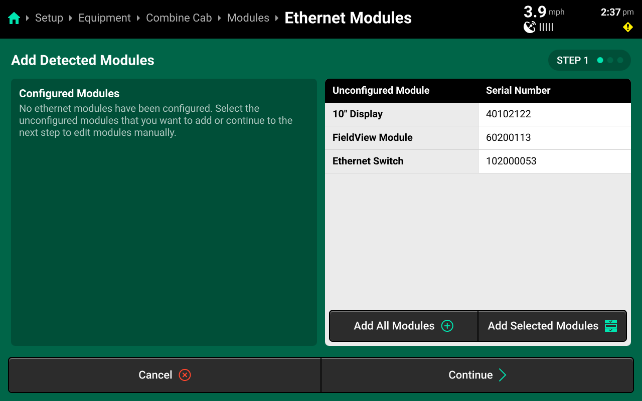
If all Ethernet modules are detected correctly in the left window, press Add All Modules + in the bottom of the right window on Step 1 to confirm and save auto-detected modules. To add only select modules, press each desired module in the left window, then press Add Selected Modules to confirm and save each highlighted module.
The Ethernet Switch is a new device that is not required for combines. The images in this guide are for illustration purposes only.
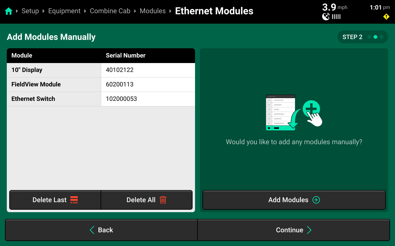
(Optional)
If Ethernet modules will be connected later, modules may be set up manually on Step 2 if desired. When using manual setup, it will be necessary to know the serial number of the manually added modules for the next step. Press Add Modules + in the right window and select the correct module from the popup.
If all modules were detected correctly on Step 1, press Continue without adding modules to skip Step 2.
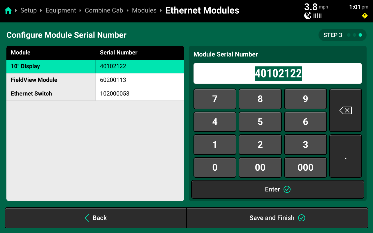
Confirm or enter correct serial number for each device on Step 3. Press Save and Finish to exit setup and return to Modules. Ensure that Ethernet devices are listed correctly below DBM in the left window.
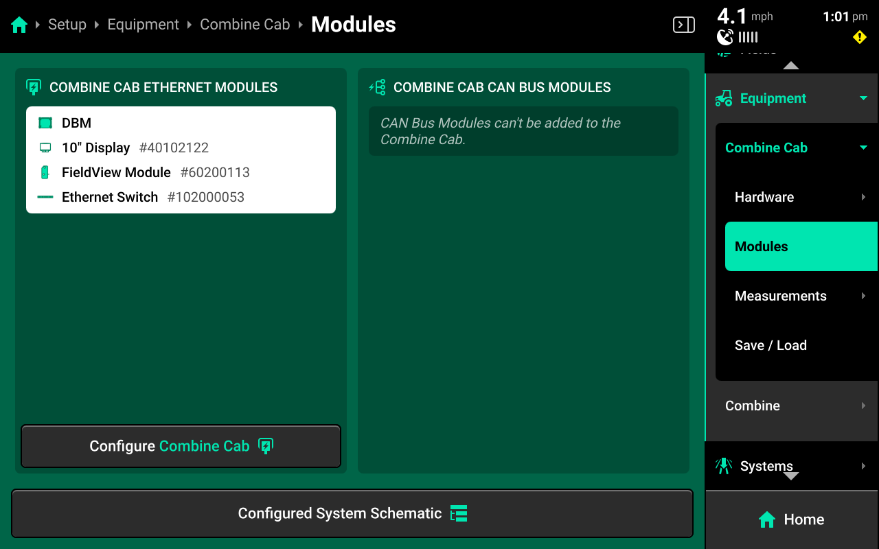
Ethernet modules may also be added to the implement. This is intended for Ethernet switches and Vision cameras. Configure all displays and FieldView Modules on the Cab to ensure correct function.
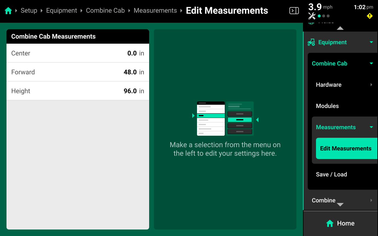
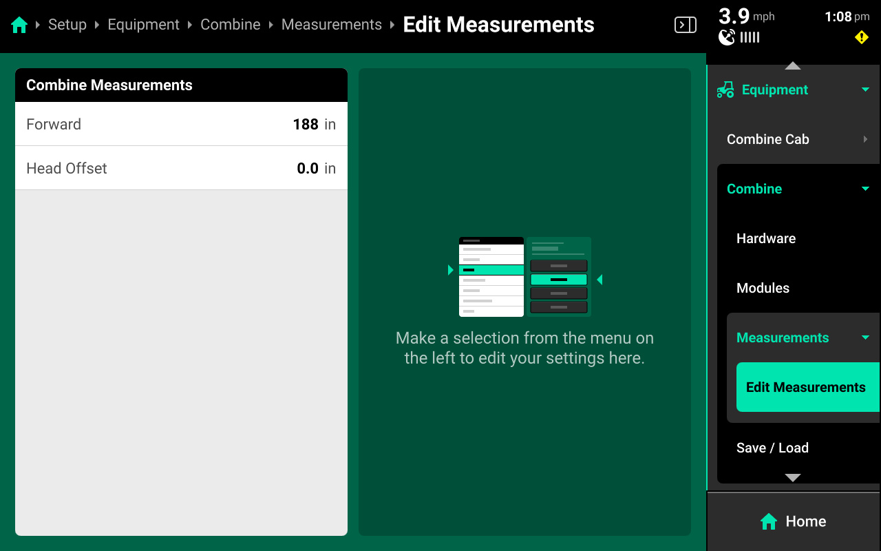
Measurements
Press Edit Measurements under Measurements in the navigation menu to view and modify all Combine Cab measurements.
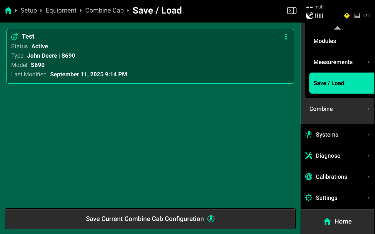
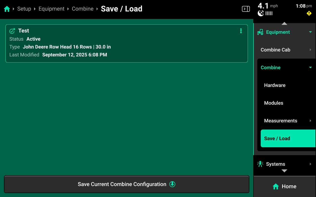
Save / Load
Press Save Current Combine Cab Configuration to name and save the current cab. Press the three dots on any existing profile to Load, Update (Save Changes), or Delete the current cab profile.
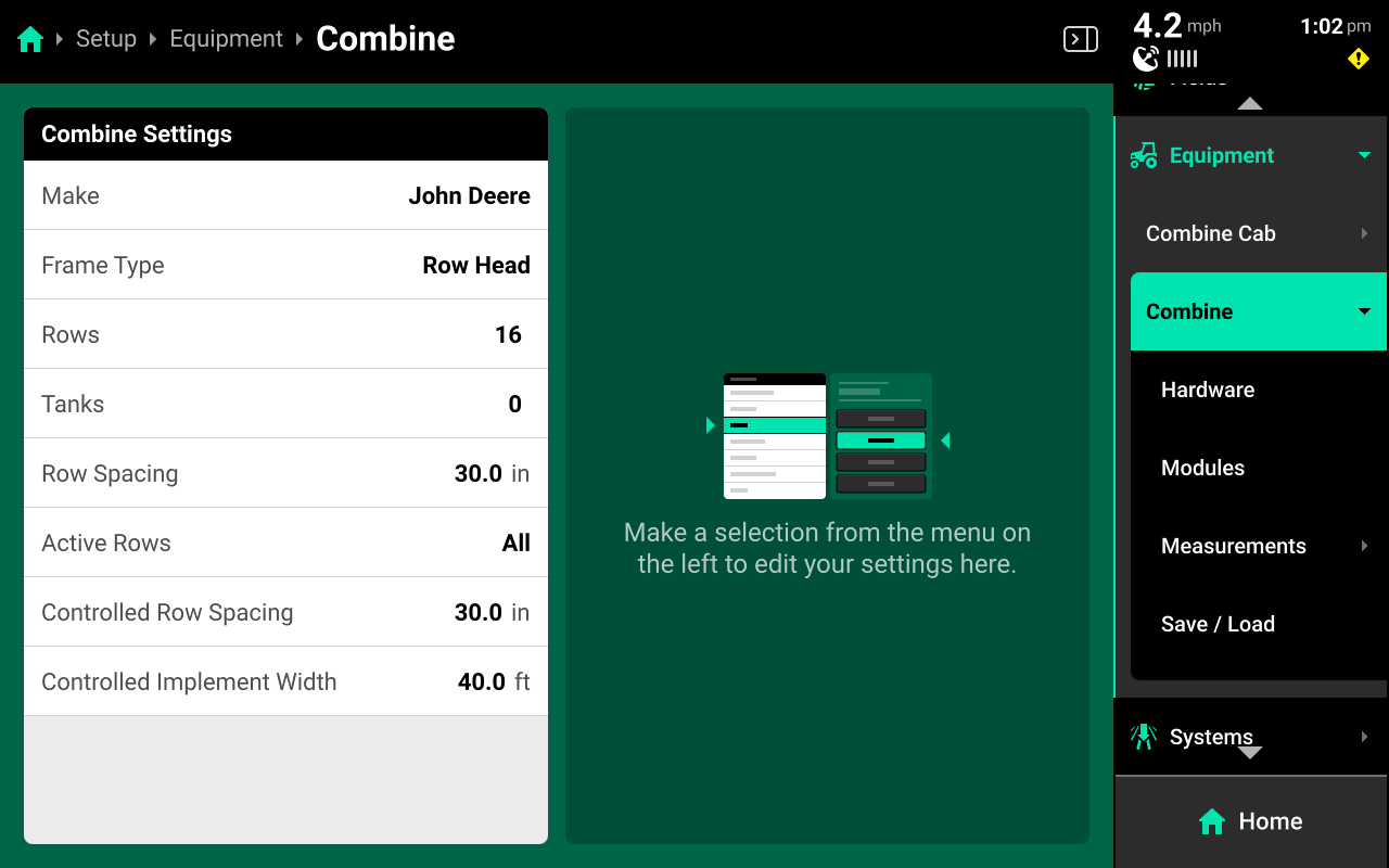
Combine Head
Navigate to Setup > Equipment > Combine to configure the Combine Head make, type and rows.
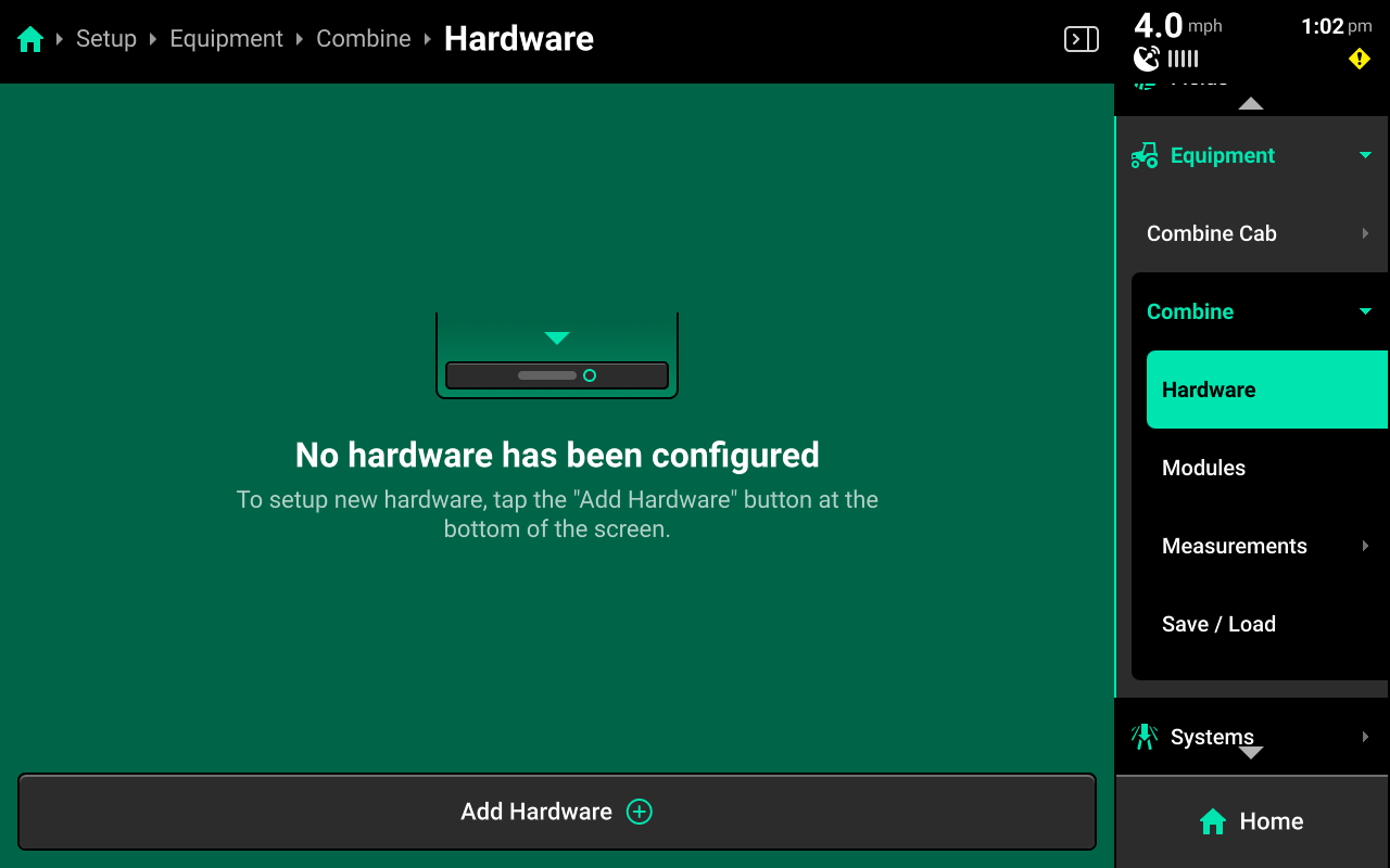
Hardware
Do not configure any hardware on the Combine Head. If GPS is added to the Combine Head by accident, navigate to Setup > Equipment > Combine Cab > Hardware and add GPS to the cab to remove it from the head.
Modules
Navigate to Setup > Equipment > Combine > Modules to set up CAN modules.
Configure all CAN modules (YSM, BXM) on the Combine Cab using the following process.
The Blockage Expansion Module [BXM] is not commonly used on Combines. BXM setup will not be covered in this guide.
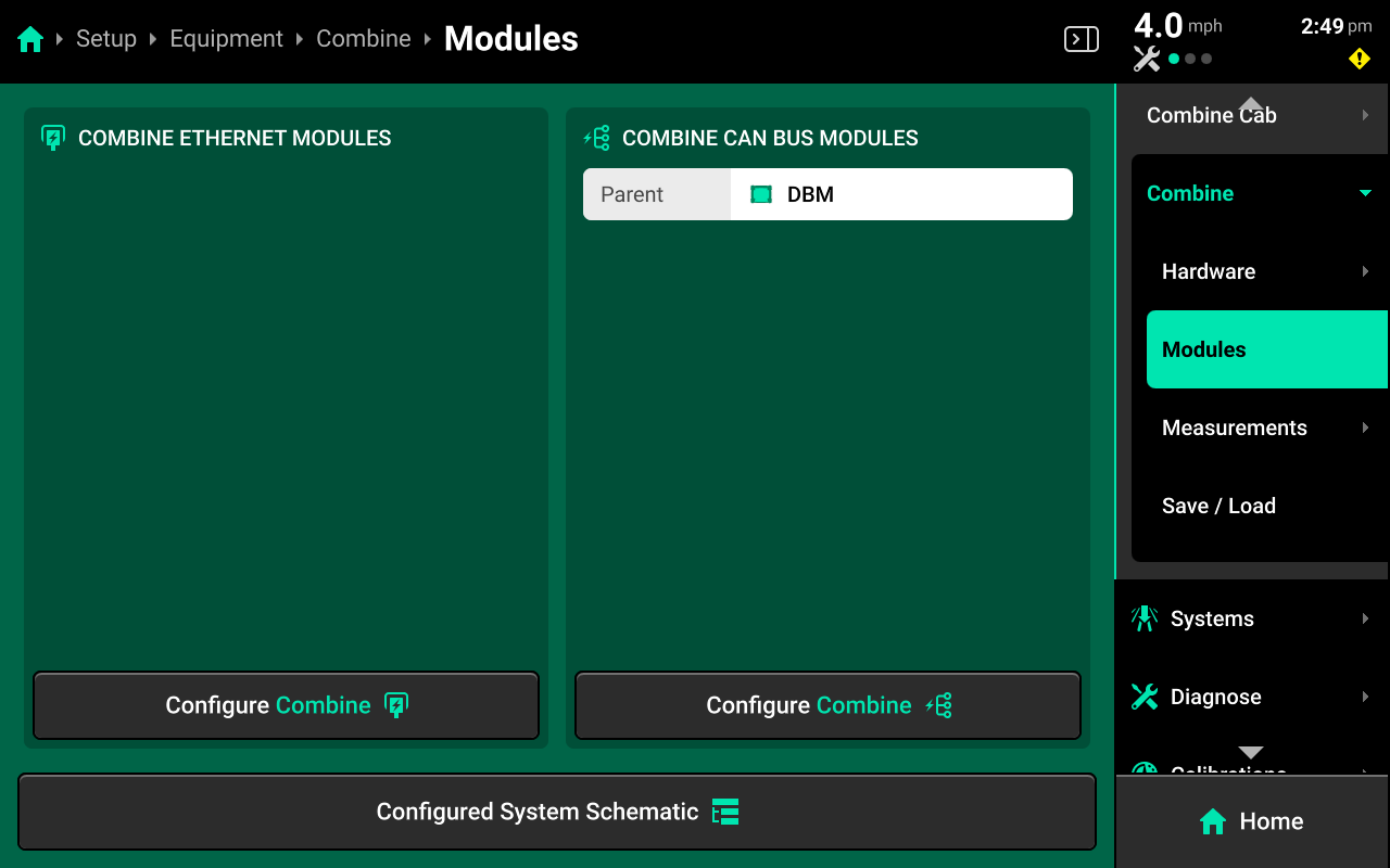
Press Configure Combine in the Combine CAN Bus Modules window in the right center screen to set up the YieldSense CAN bus.
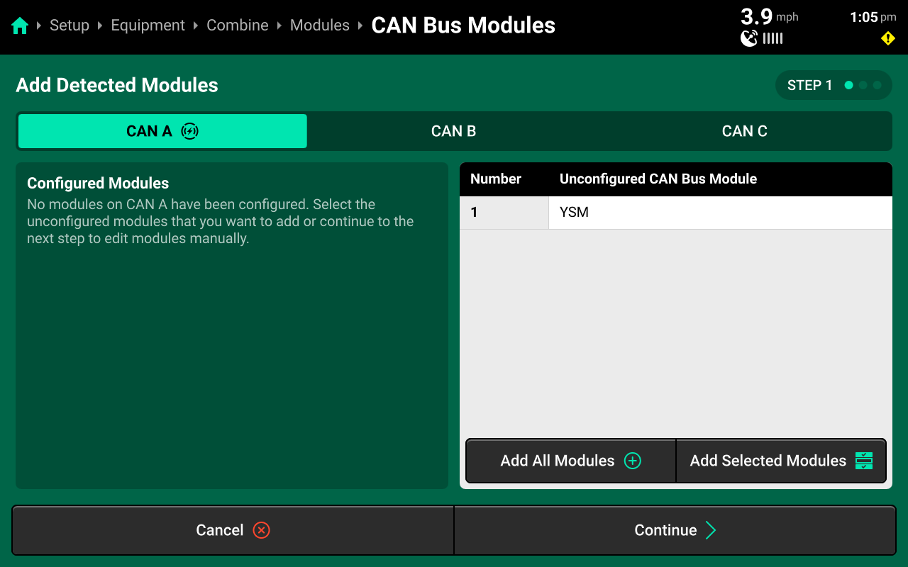
If the YSM is detected in the left window on Step 1, press Add All Modules+ in the bottom of the right window to confirm and save it. Then press Continue.
(Optional)
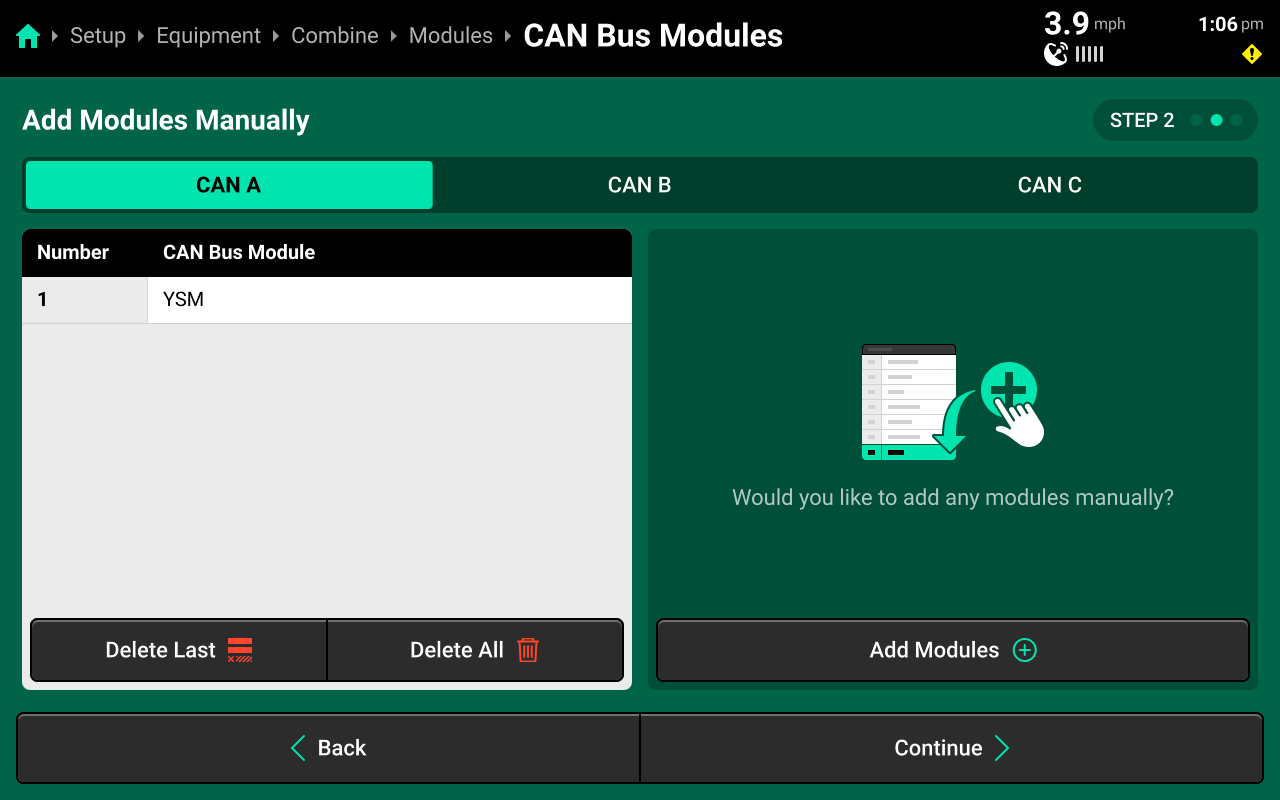
If the YSM will be connected later, it may be configured manually on Step 2. Press Add Modules+ in the right window and select the YSM from the popup, enter 1 using the popup keyboard, then press Continue in the bottom right.
If the YSM was detected correctly on Step 1, press Continue without adding modules to skip Step 2.
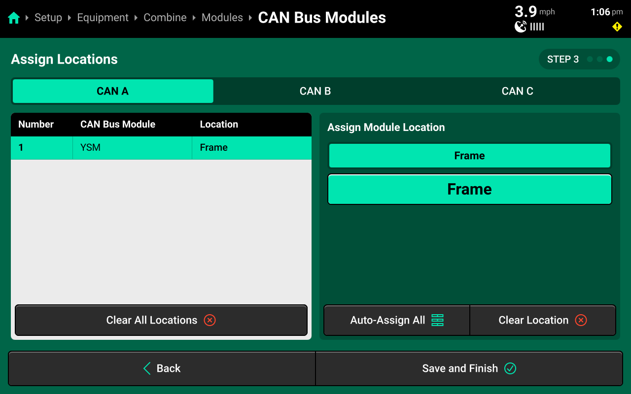
On Step 3, press Auto-Assign All to assign the correct location (Frame) to the YSM, then press Save and Finish to exit CAN module setup. Ensure that the YSM is displayed correctly below the DBM in the right window.
Measurements
Press Edit Measurements under Measurements in the navigation menu to view and modify all Combine Head measurements.
Save / Load
Press Save Current Combine Cab Configuration to name and save the current head. Press the three dots on any existing profile to Load, Update (Save Changes), or Delete the current head profile.
System Setup
YieldSense requires a Harvest system to be configured in the 20|20, in addition to the default Combine system.
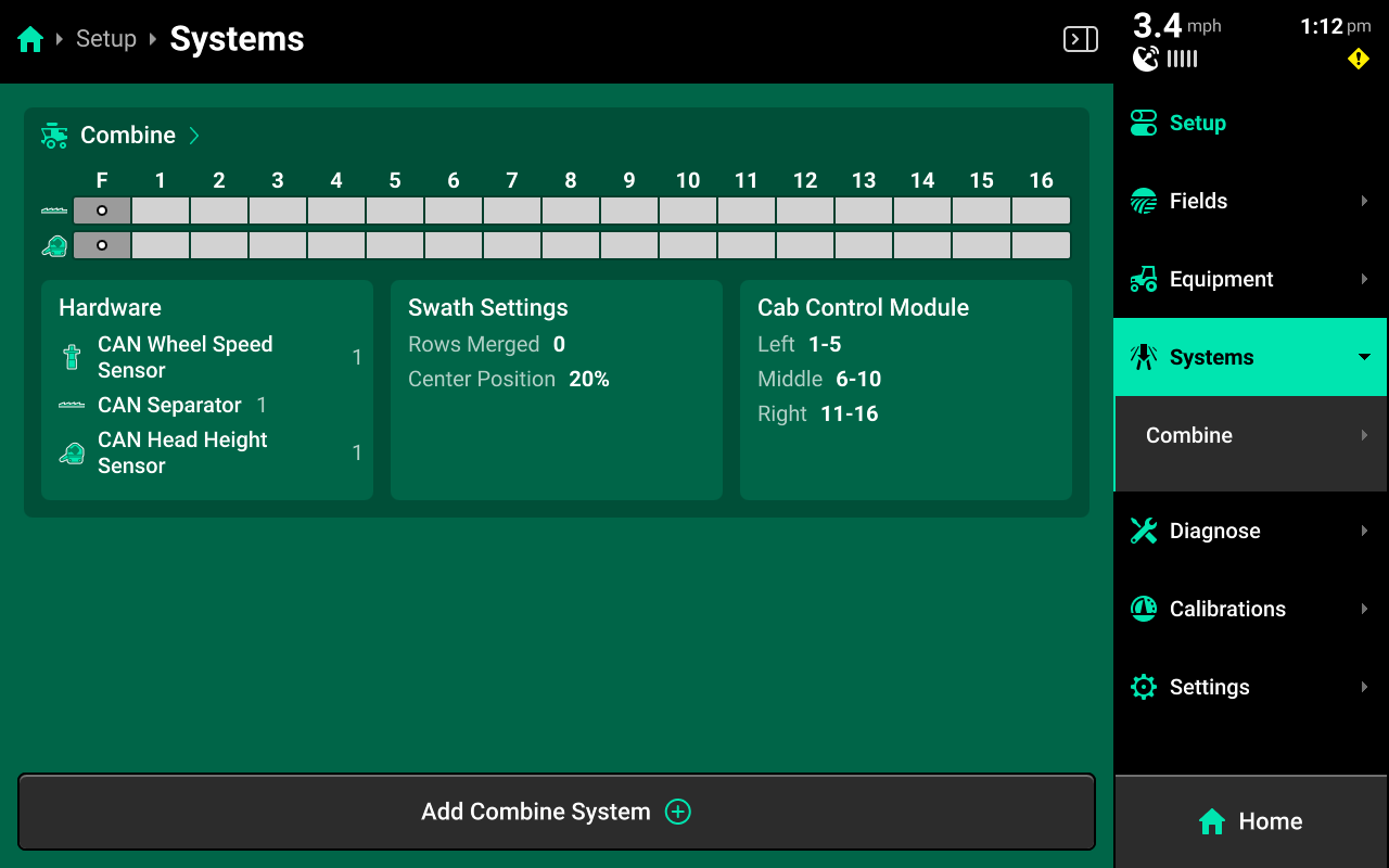
Combine (Default) System
Select Combine under Systems in the Navigation Menu to configure the default implement system.
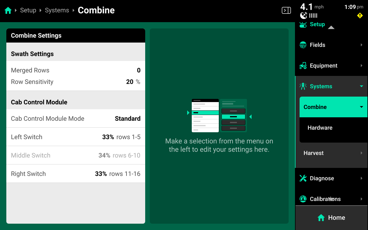
Use the options displayed in the left window to merge rows together in low-accuracy GPS situations, or to set up custom CCM control. See 2025.1.x Gen 3 20|20 Operator's Guide for more information on merging rows and customizing the CCM.
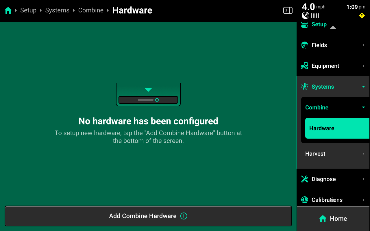
Hardware Setup
Select Hardware under Combine in the Navigation Menu to configure system hardware.
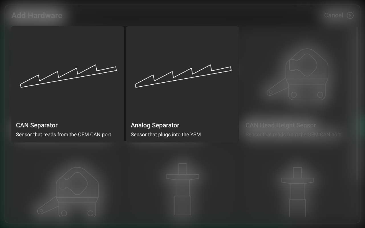
CAN / Analog Separator
If setting up YieldSight on a Gleaner S or T series combine, do not set up a separator.
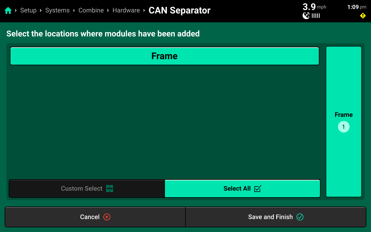
Press Add Combine Hardware+ and select CAN or Analog Separator from the popup to open the hardware setup wizard.
Select Frame for the module location, then press Save and Finish to exit the setup wizard.
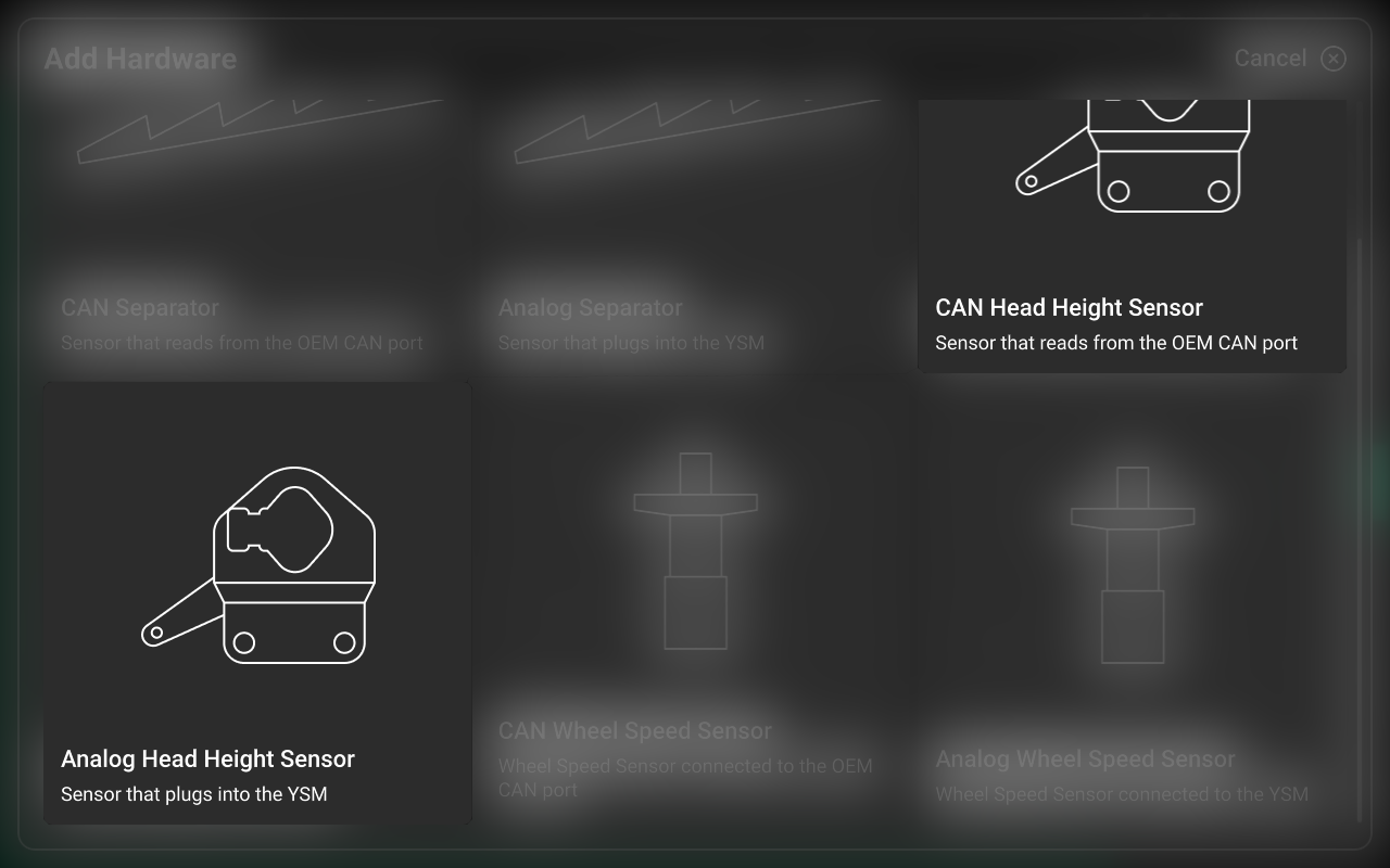
CAN / Analog Head Height Sensor
Press Add Combine Hardware+ and select CAN or Analog Head Height Sensor from the popup to open the hardware setup wizard.
Select Frame for the module location on Step 1, then press Continue.

Review settings on Step 2, then press Save and Finish to exit the setup wizard.
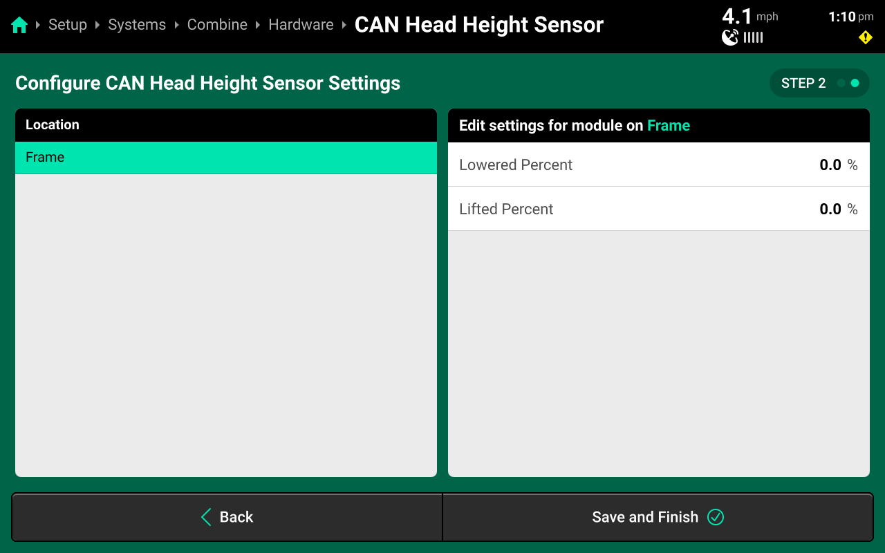
Do not manually change Lifted / Lowered Percent on this step. The values for each percent will be determined later in System Calibrations.
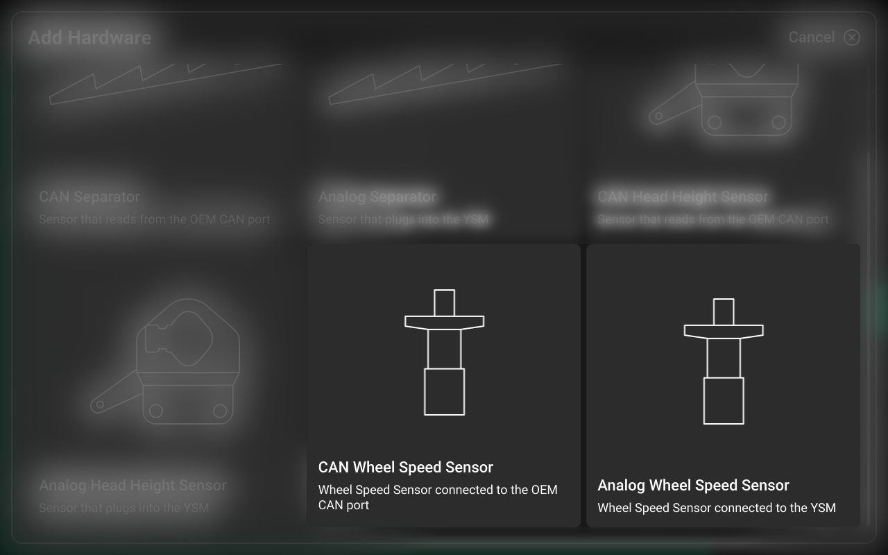
CAN / Analog Wheel Speed Sensor
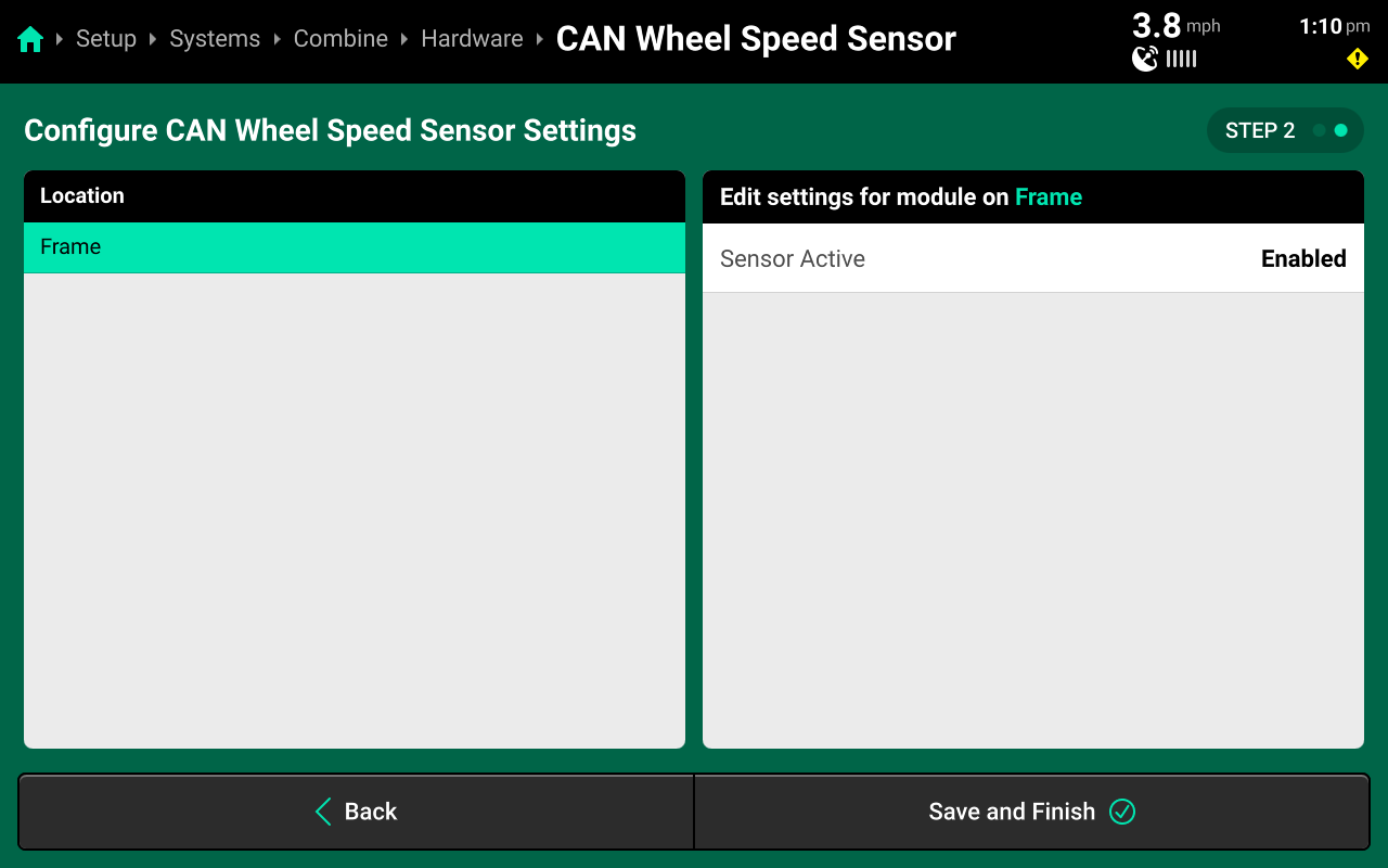
Press Add Combine Hardware+ and select CAN or Analog Wheel Speed Sensor from the popup to open the hardware setup wizard.
Select Frame for the module location on Step 1, then press Continue.
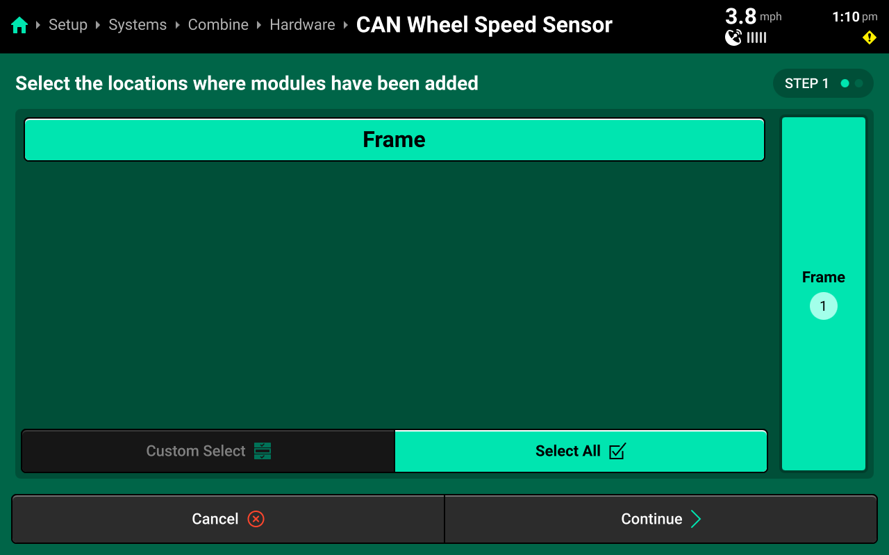
Review settings on Step 2, then press Save and Finish to exit the setup wizard. The sensor should remain enabled unless it is malfunctioning.
Harvest System
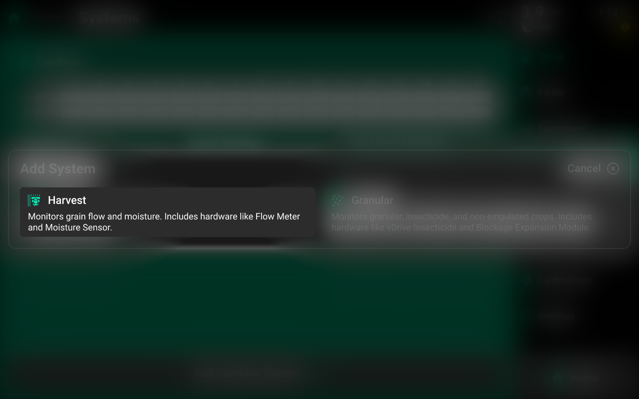
Navigate to Setup > Systems and press Add Combine System at the bottom to configure the Flow Sensor and Moisture Sensor.
Select Harvest from the popup, then select a preset name or enter a custom name from the second popup.
Select [Harvest System Name] in the Navigation Menu to begin configuration.
Hardware Setup
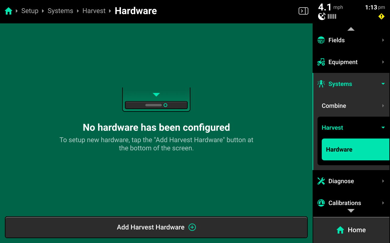
To configure system hardware, press Hardware under [Harvest System Name] in the Navigation Menu and use the following process.
CAN / Analog Flow Sensor
Press Add [System Name] Hardware + and select CAN or Analog Flow Sensor to open the hardware setup wizard
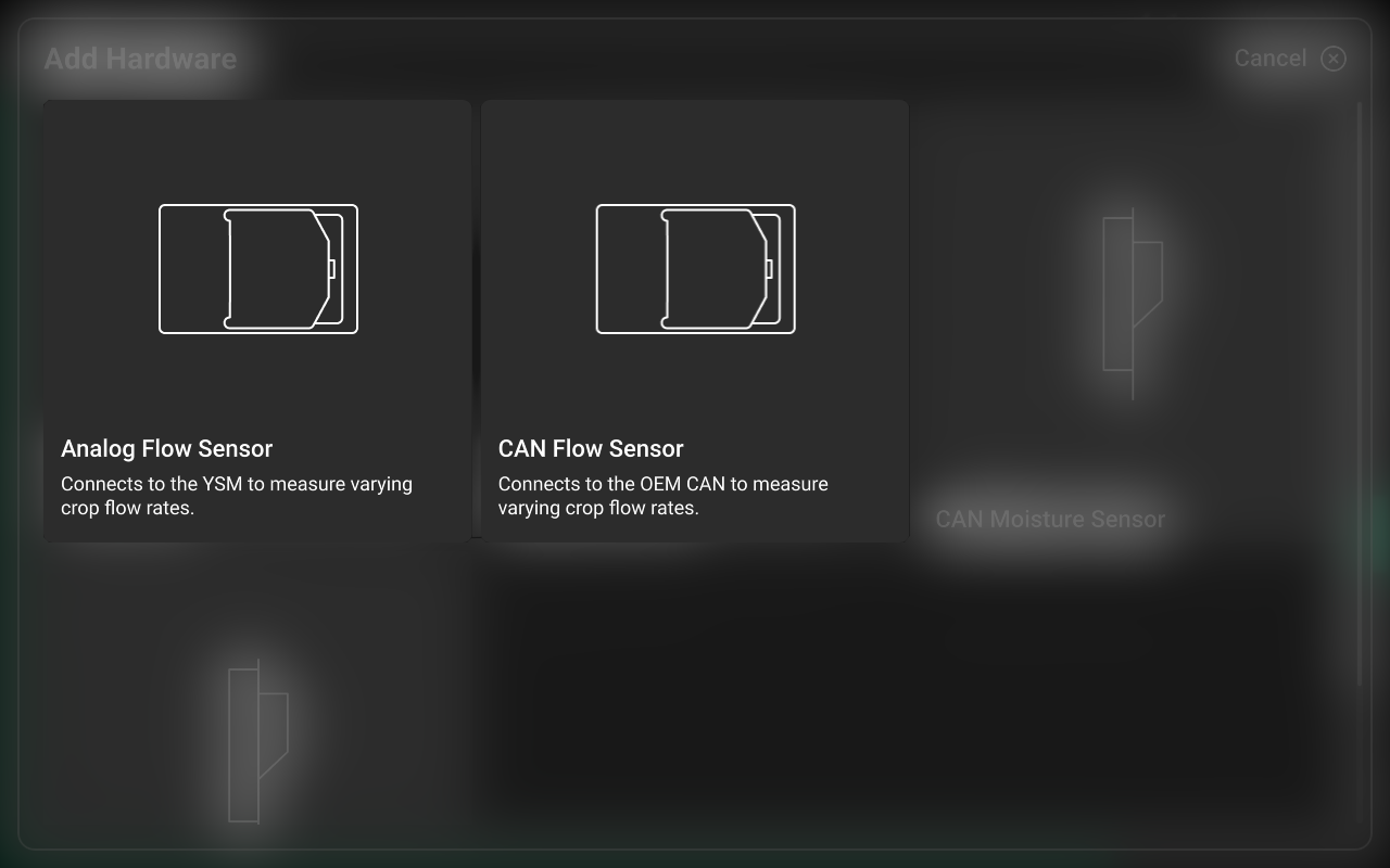
Select CAN Flow Sensor only if using the new YieldSight system. All classic YieldSense systems will utilize the Analog Flow Sensor.
Select Frame for the module location on Step 1, then press Continue.

Review and modify settings on Step 2, then press Save and Finish to exit the setup wizard.
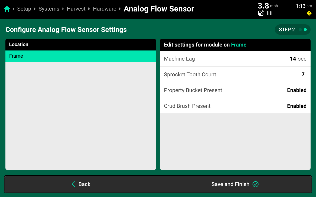
- Machine Lag : Changes the amount of time used to translate data from the flow sensor to the correct map location. Modify this value when seeing inaccurate mapping across known areas of yield variation (e.g. waterways). See the image below for an example.
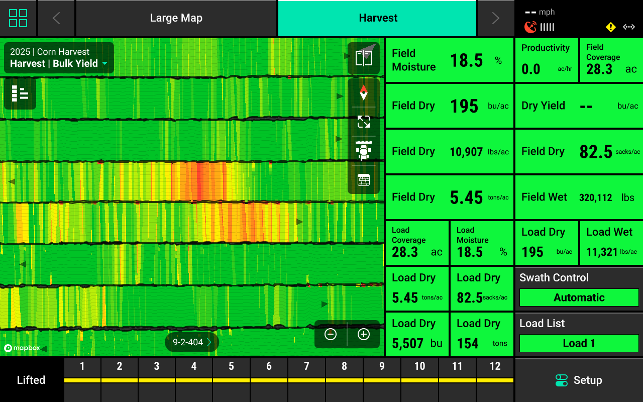
In the pictured situation, the two lower-yield areas in red should align from pass-to-pass instead of being offset. Increase the Machine Lag to improve mapping on future passes.
- Sprocket Tooth Count : Sets the number of teeth on the lower sprocket of the elevator chain.
This value must be changed to the appropriate count for every YieldSense installation.
- Property Bucket Present : This value should be set to Present unless the property bucket is damaged, missing, or not installed (JD 9400 / 9500).
- Crud Brush Present : This value should be set to Present unless the crud brush in damaged or missing.
CAN / Analog Moisture Sensor
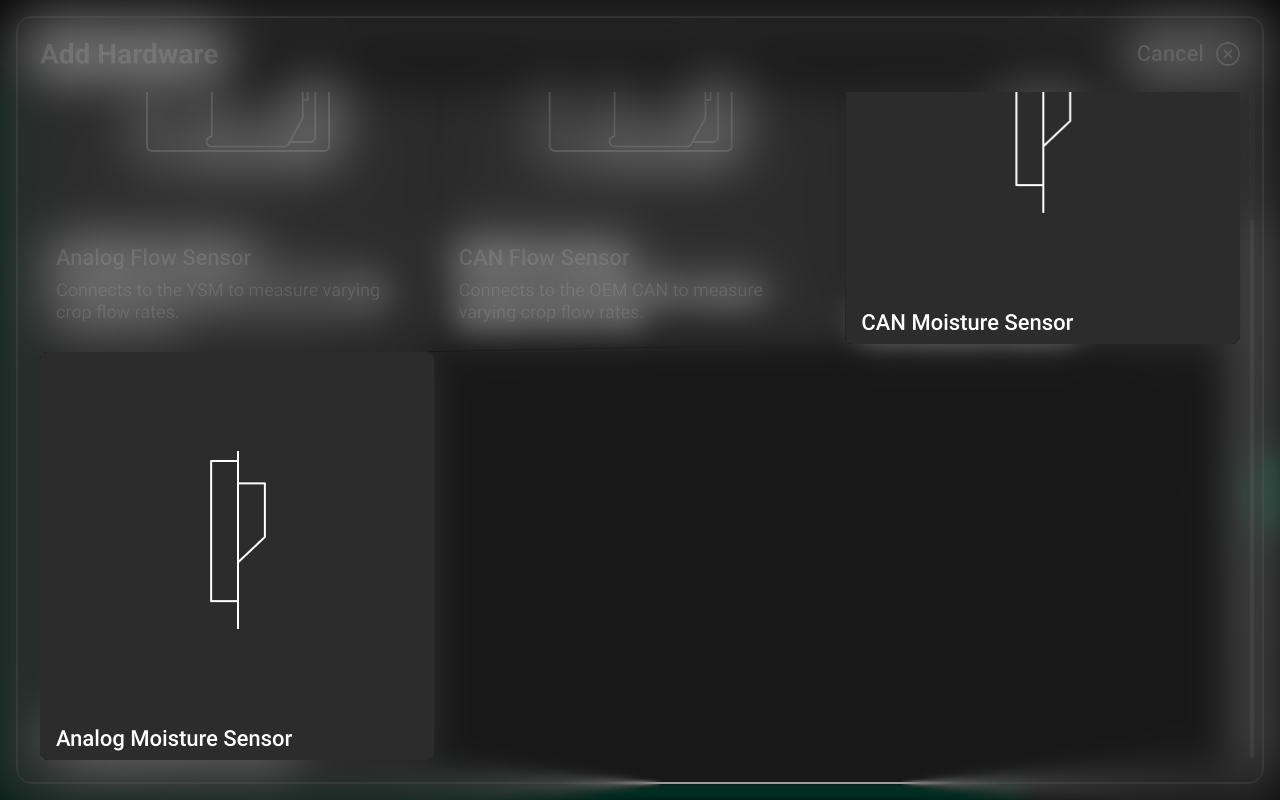
Press Add [System Name] Hardware + and select CAN or Analog Moisture Sensor to open the hardware setup wizard
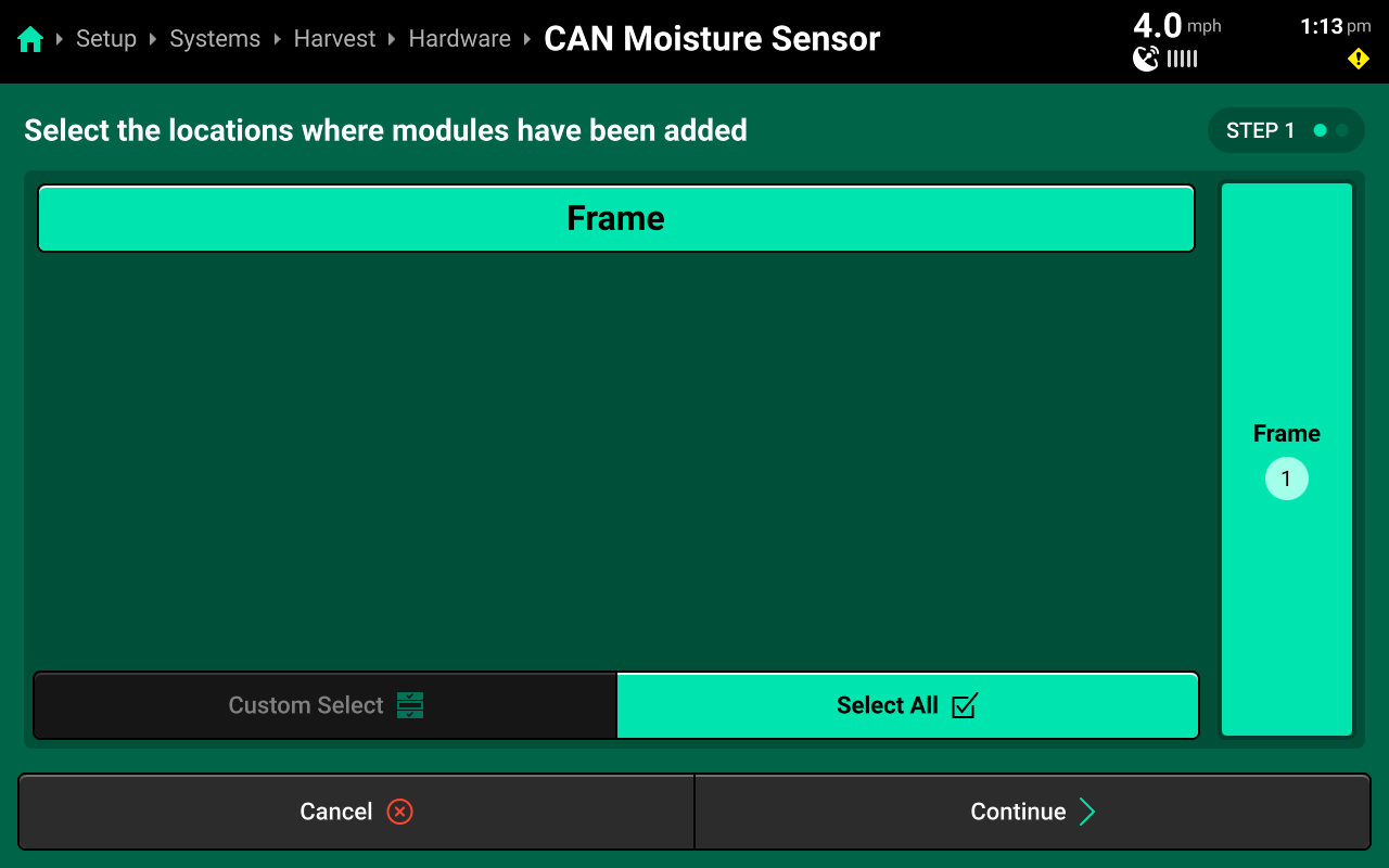
Select Frame for the module location on Step 1, then press Continue.
Review and modify settings on Step 2, then press Save and Finish to exit the setup wizard.
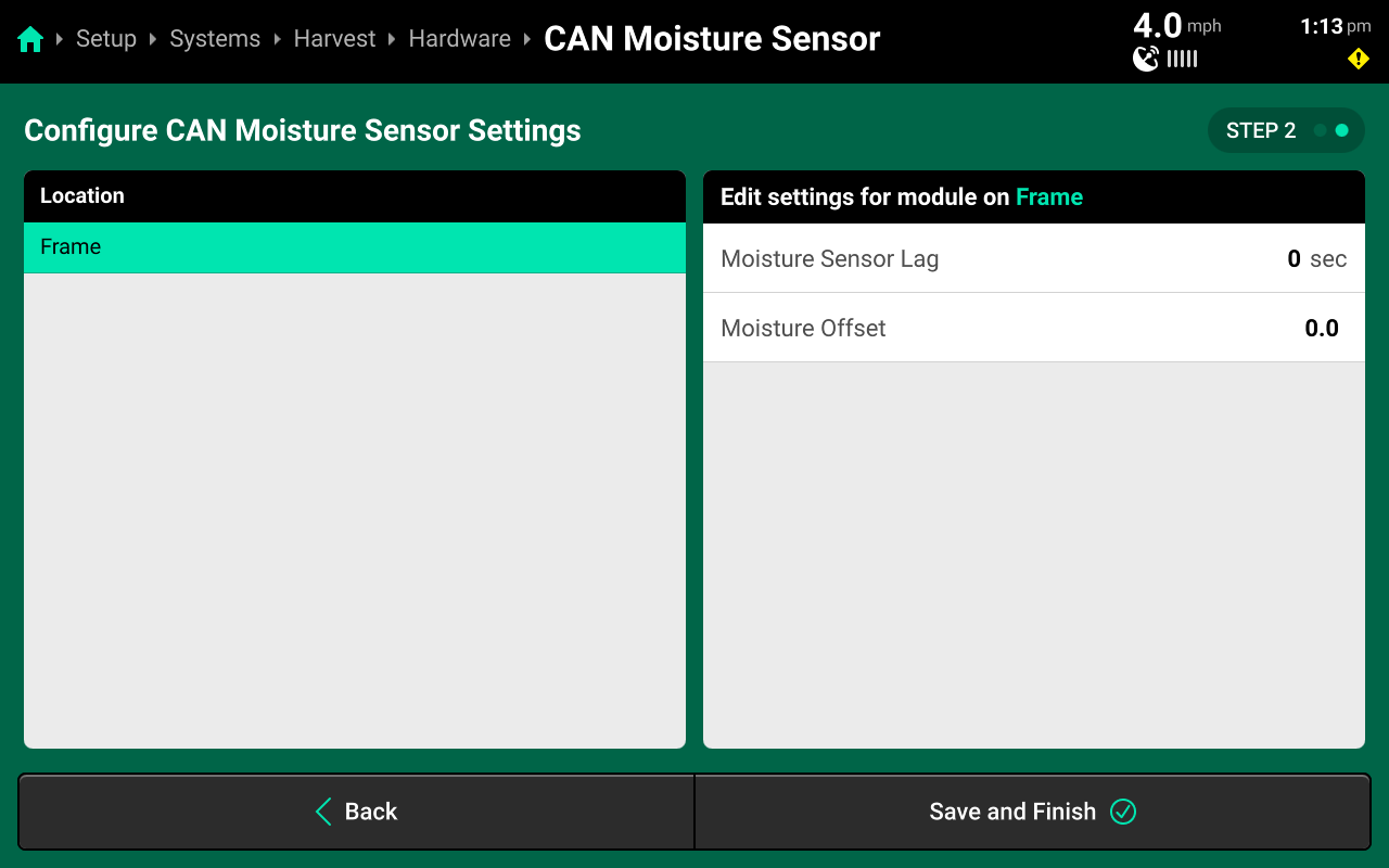
- Moisture Sensor Lag : Changes the amount of time used to translate data from the moisture sensor to the correct map location. Modify this value when seeing inaccurate mapping across areas of known moisture variation.
- Moisture Offset : Modifies moisture sensor reading to address discrepancies between OEM moisture readings and 20|20 moisture readings.
System Settings
After hardware setup is complete, press [Harvest System Name] in the Navigation Menu to adjust system settings.
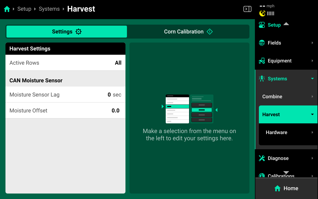
Select a setting in the left window and modify the setting using the right window.
- Active Rows : Sets the current active rows for the system
Operation Settings
- Moisture Sensor Lag : Changes the amount of time used to translate data from the moisture sensor to the correct map location. Modify this value when seeing inaccurate mapping across areas of known moisture variation.
- Moisture Offset : Modifies moisture sensor reading to address discrepancies between OEM moisture readings and 20|20 moisture readings.
Granular System
A Granular system may be configured in Combine Mode to control / monitor granular product application from a combine. Granular system setup is not covered in this guide. See the DrySet Micro Operator's Guide for granular monitoring setup.
Crop Calibration
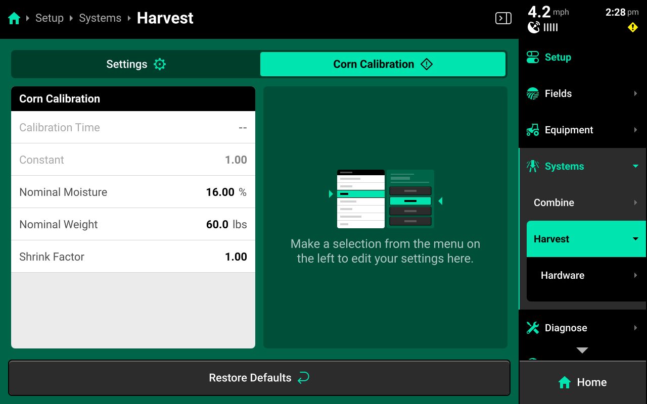
Use the tab at the top of [Harvest System Name] to view the crop-specific calibration values for YieldSense. All crops have the same default settings, but any changes made will be saved to the specific crop. Different crop calibration values are saved for each Implement profile. Press Restore Defaults at the bottom to reset crop calibration settings.
- Calibration Time : Date of last calibration. Non-functional as of 2025.1.7.
- Constant : Calibration value of the flow sensor.
- Nominal Moisture : Moisture percentage that the harvested grain will be dried to.
- Nominal Weight / Shrink Factor : The values used in bushel calculation
System Calibrations
Navigate to Setup > Calibrations to perform calibration of the mechanical and positional components of the YieldSense system.
GPS Offset Check
See the 2025.1.x Gen 3 20|20 Operator's Guide for the GPS Offset Check process.
As of 2025.1.7, the GPS Offset Check for Combines does not display the user-entered measurements on the final step of the GPS offset check. It is necessary to record the measured values, then navigate to Setup > Equipment > Combine Cab / Combine (Head) to review / modify the appropriate measurements. This will be addressed in a future version of software.
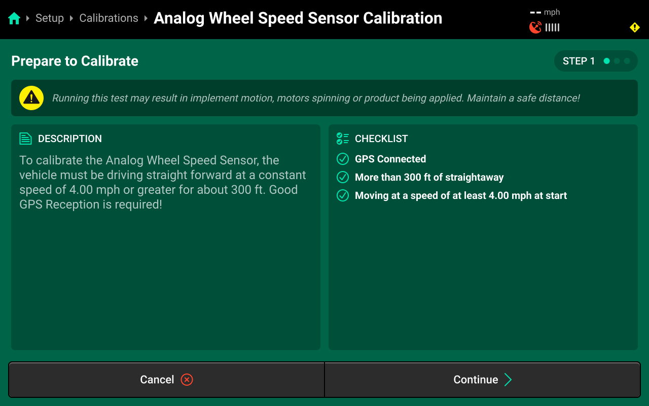
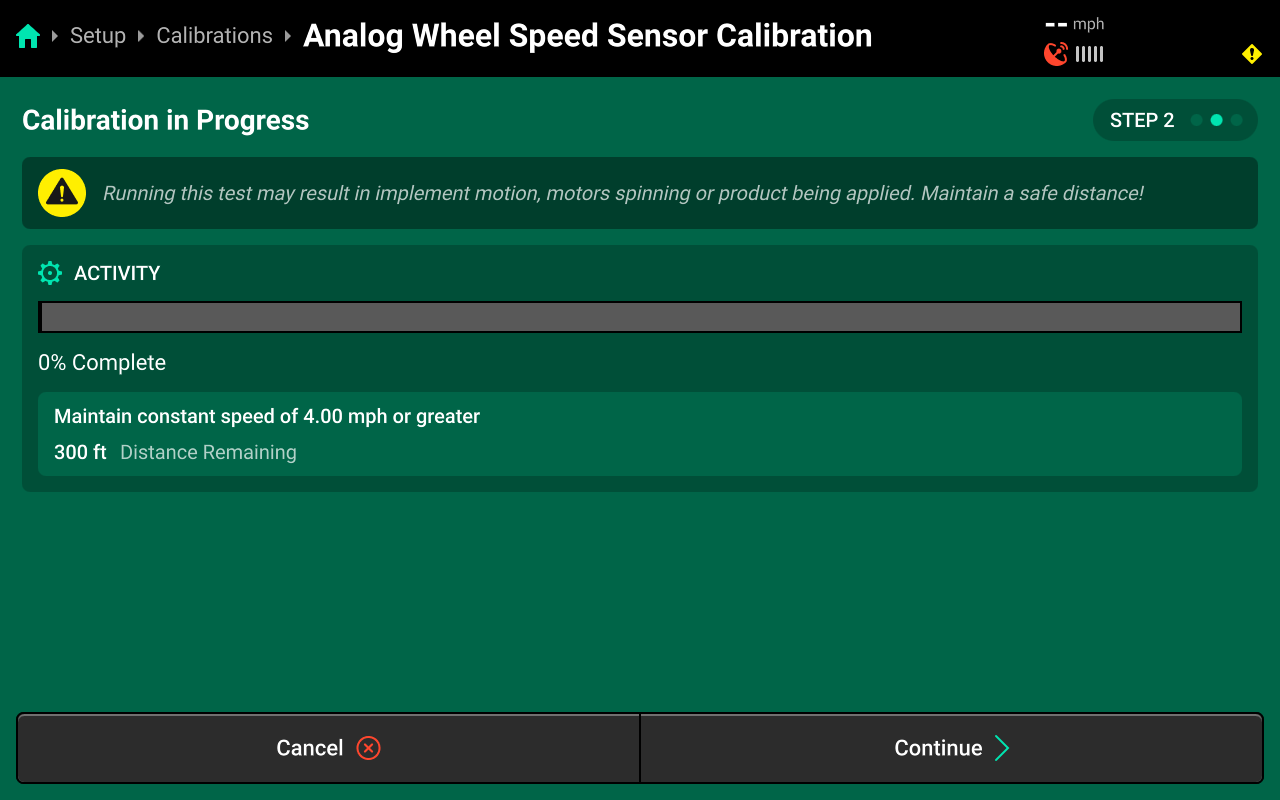
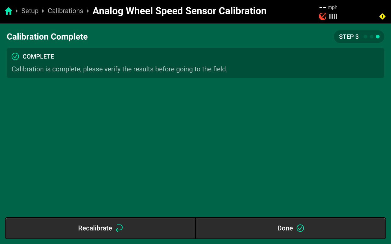
CAN / Analog Wheel Speed Sensor Calibration
Run the calibration wizard to set pulses / foot for the wheel speed sensor. Good GPS signal is required. Once the bar fills, the calibration is complete. Navigate to Setup > Diagnose > Combine Cab > GPS and scroll on the center screen to confirm that GPS and Wheel speed match. Perform the calibration again if necessary.
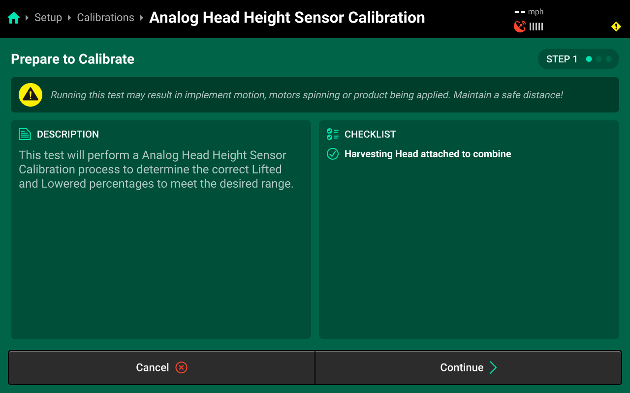
CAN / Analog Head Height Sensor Calibration
Do not calibrate the CAN head height sensor when using YieldSight on Gleaner or Fendt combines.
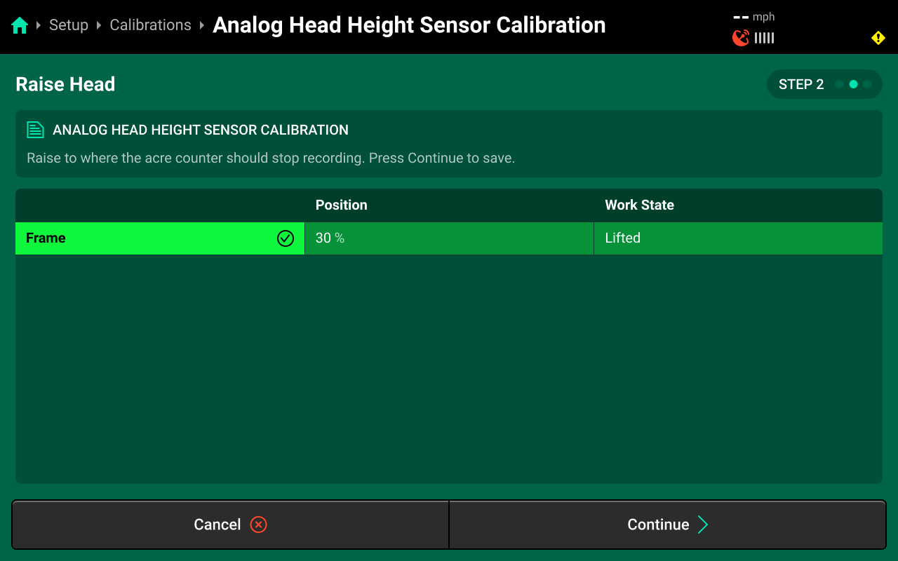
Run the calibration wizard to perform calibration of the head height sensor. Set Raised height on Step 2.
Lowered

Lifted
Confirmation
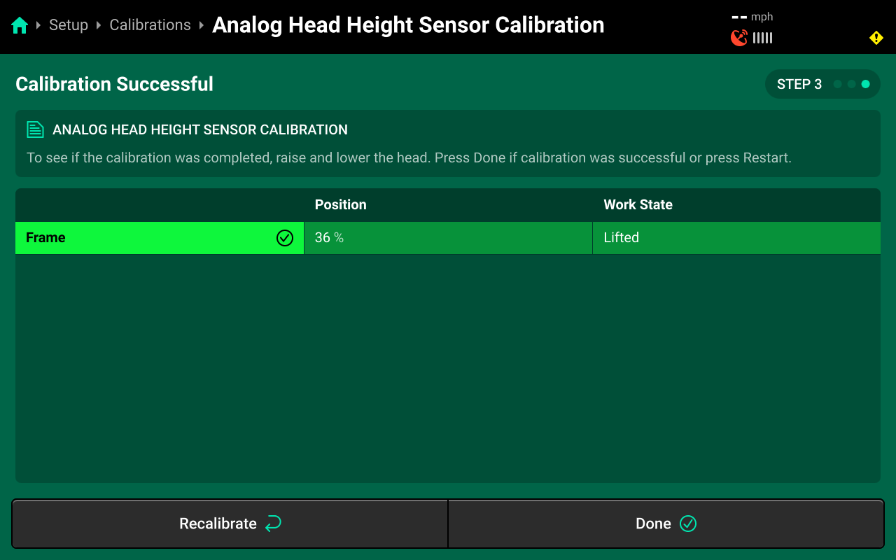
Use step 3 to raise / lower the implement and confirm correct position readings before exiting the wizard.
Diagnostics
Diagnose Menu Overview
The Diagnose Menu is used to identify and troubleshoot hardware device failures and configuration issues in the 20|20.
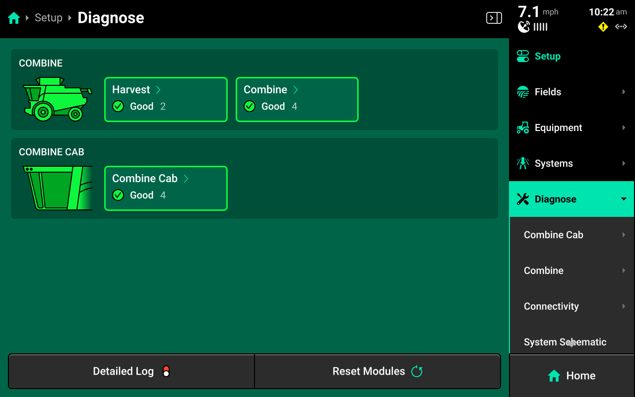
Use the following colors to determine device status on the Diagnose screen.
- Green : Device is working correctly. Communications are good.
- Yellow : Device or sub-component is not 100% functional.
- Red : Device has failed, or is expected and not detected.
- White : Device is detected but not expected.
- Black : Device has been disabled by the user.
- Grey : Device is finishing detecting or unreachable.
- Teal : Device is updating firmware.
Press Reset Modules at the bottom and confirm on the popup to break and reestablish all CAN communication and daisy chain identification. This function is often used as a troubleshooting tool for communication issues.
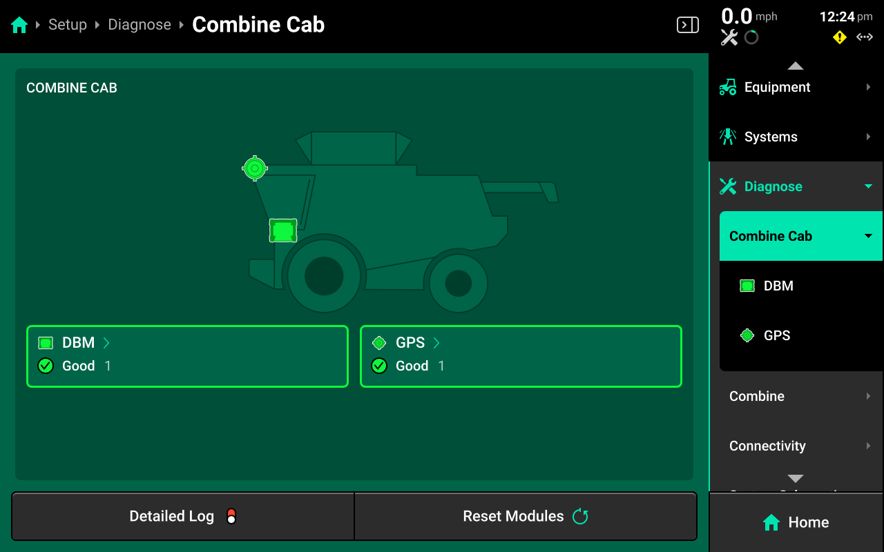
Cab Diagnostics
Cab diagnostics are not specific to YieldSense and are not covered in this guide. For detailed cab diagnostics, see the 2025.1.x Gen 3 20|20 Operator's Guide.
Combine (Head) Diagnostics
To view YieldSense diagnostics, navigate to Setup > Diagnose, then press Combine in the center screen or in the Navigation Menu.
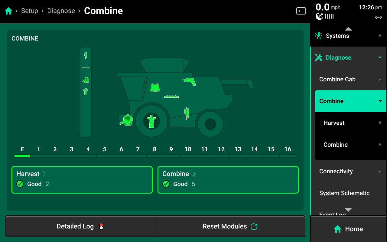
Harvest
Select [Harvest System Name] to view diagnostics for the Harvest system.
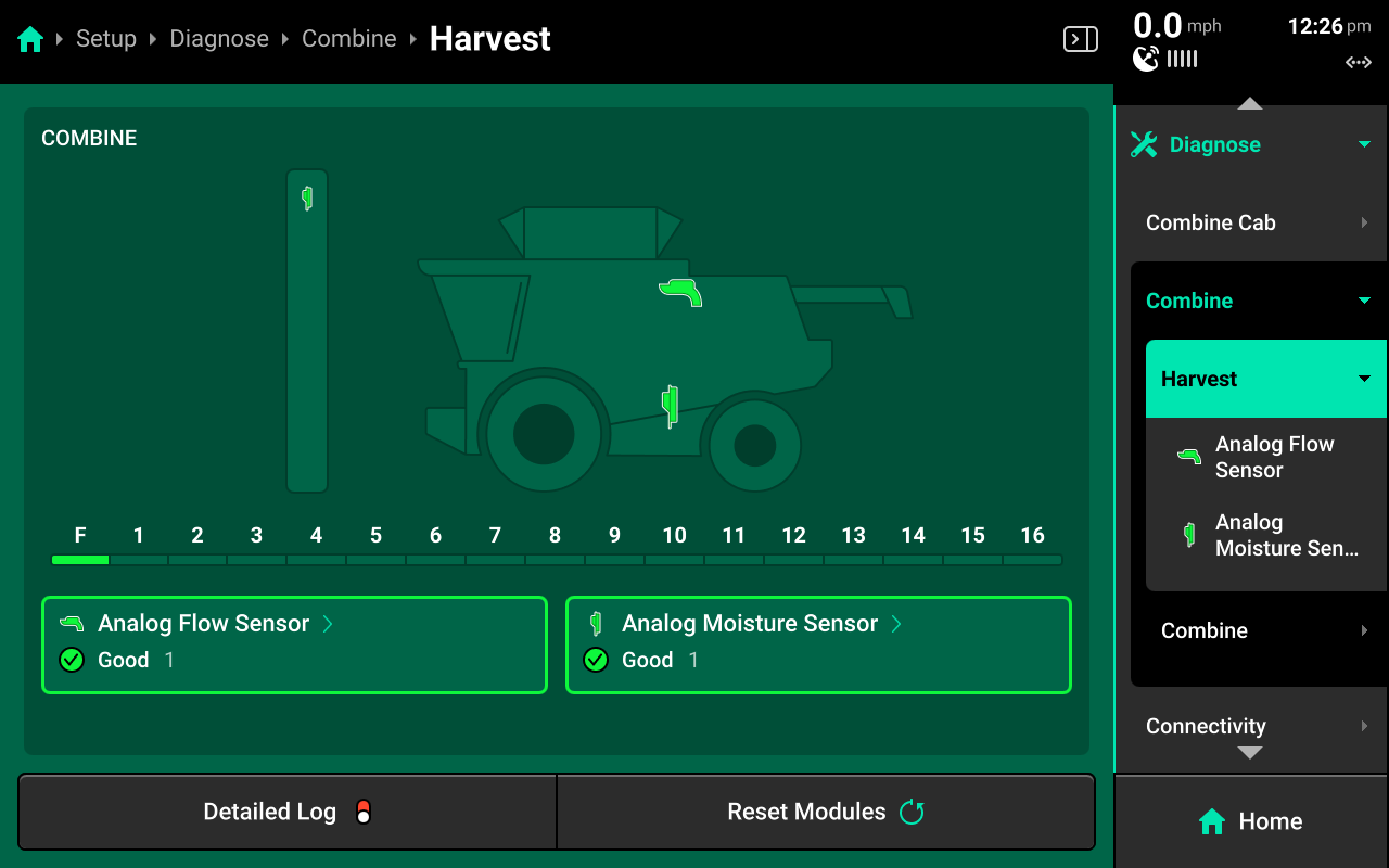
CAN / Analog Flow Sensor
Select the flow sensor to view detailed diagnostics.
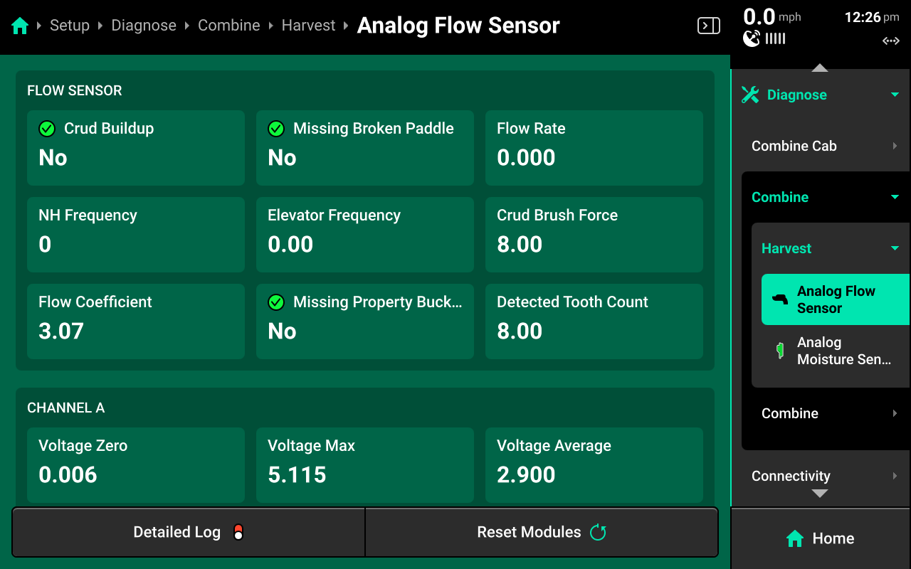
- Crud Buildup : Indicates if the flow sensor needs to be cleaned.
- Missing / Broken Paddle : Indicates if an elevator chain paddle is broken or missing.
- Flow Rate : Indicates current detected flow rate.
- NH Frequency : Frequency that the paddles are vibrating at as they throw grain agaisnt the flow sensor. Not typically used for standard diagnostics.
- Elevator Frequency : Frequency in Hz of the paddles passing by the flow sensor.
- Crud Brush Force : Impact force of the crud brush against the flow sensor.
- Flow Coefficient : Measures grain flowability. 0.2 - 1.8 is the typical expected range of values.
- Missing Property Bucket : Indicates if the Property Bucket is detected.
- Detected Tooth Count : Indicates the elevator chain sprocket tooth count detected by the 20|20.
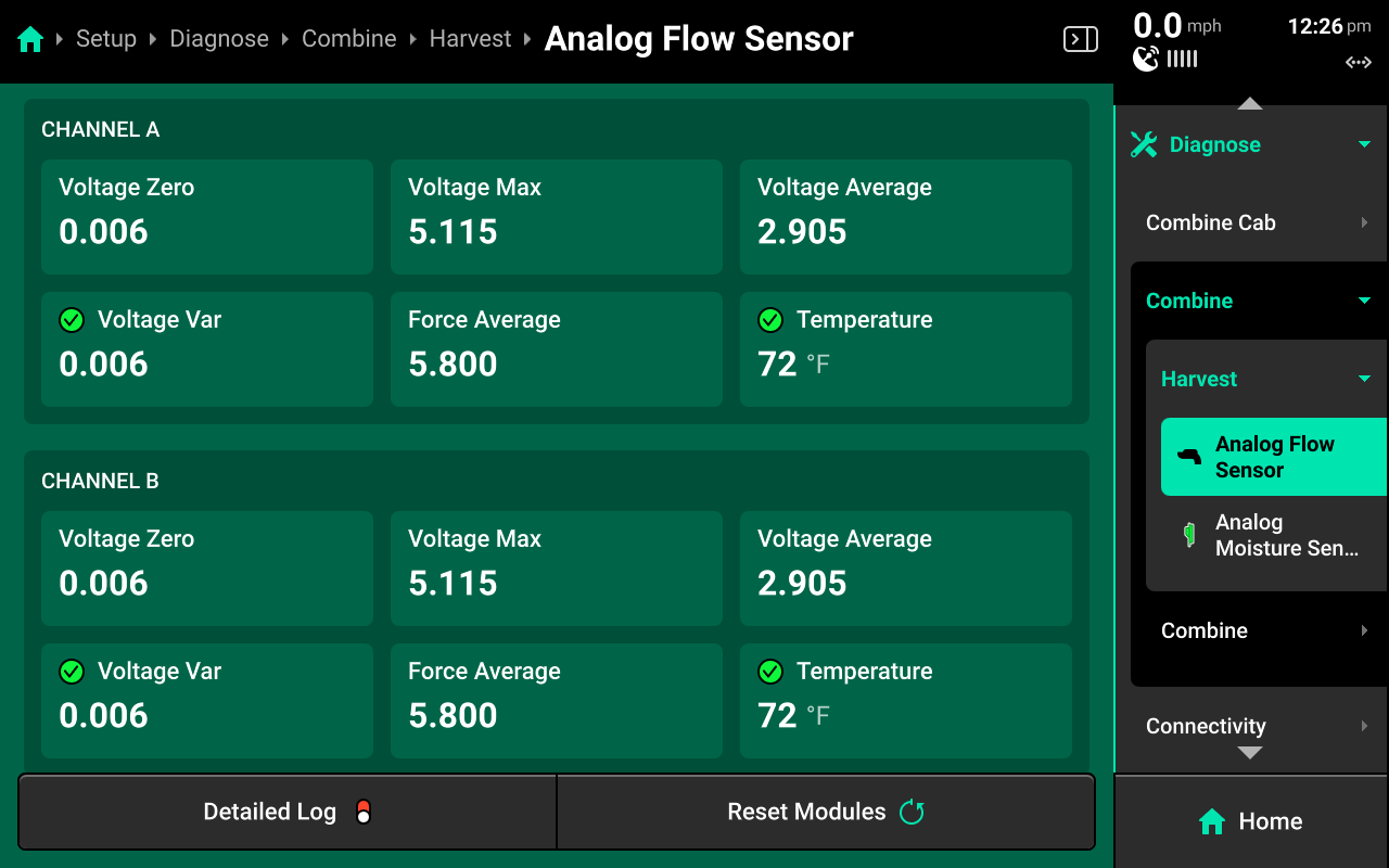
Detailed sensor readings for both channels within the Flow Sensor are also displayed on this page.
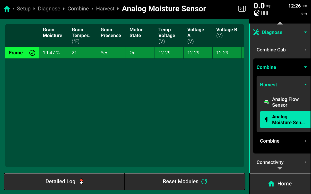
CAN / Analog Moisture Sensor
Select the moisture sensor for detailed diagnostics. Swipe across the chart to view all columns.
Combine
Select Combine to view other YieldSense diagnostics
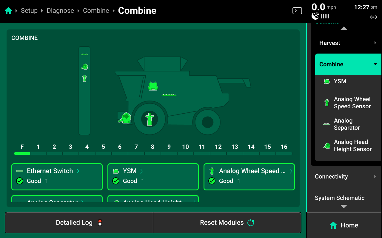
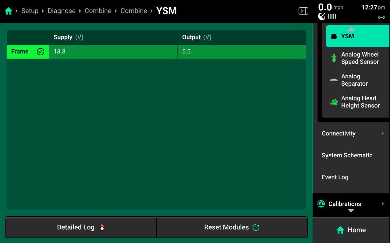
YSM
Select YSM to view voltage input / output for the YieldSense Module.
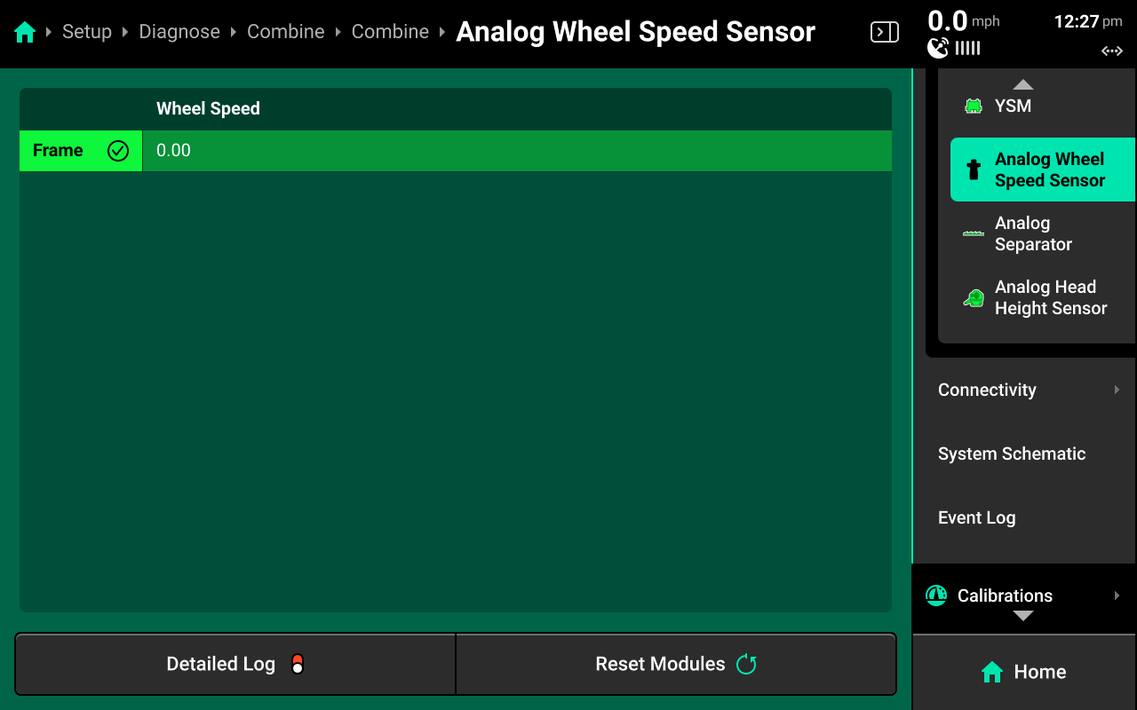
CAN / Analog Wheel Speed Sensor
Select the wheel speed sensor to view current readings from the sensor.
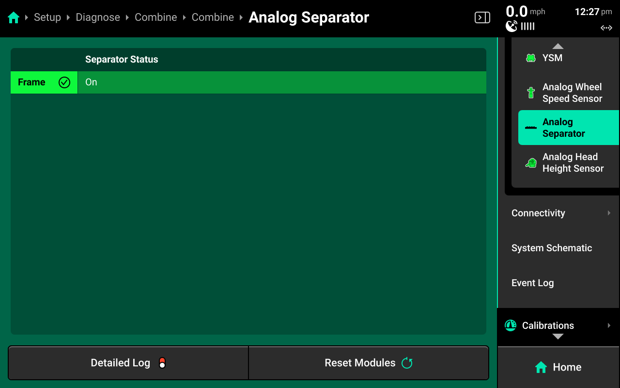
CAN / Analog Separator
Select the separator to view current separator status.
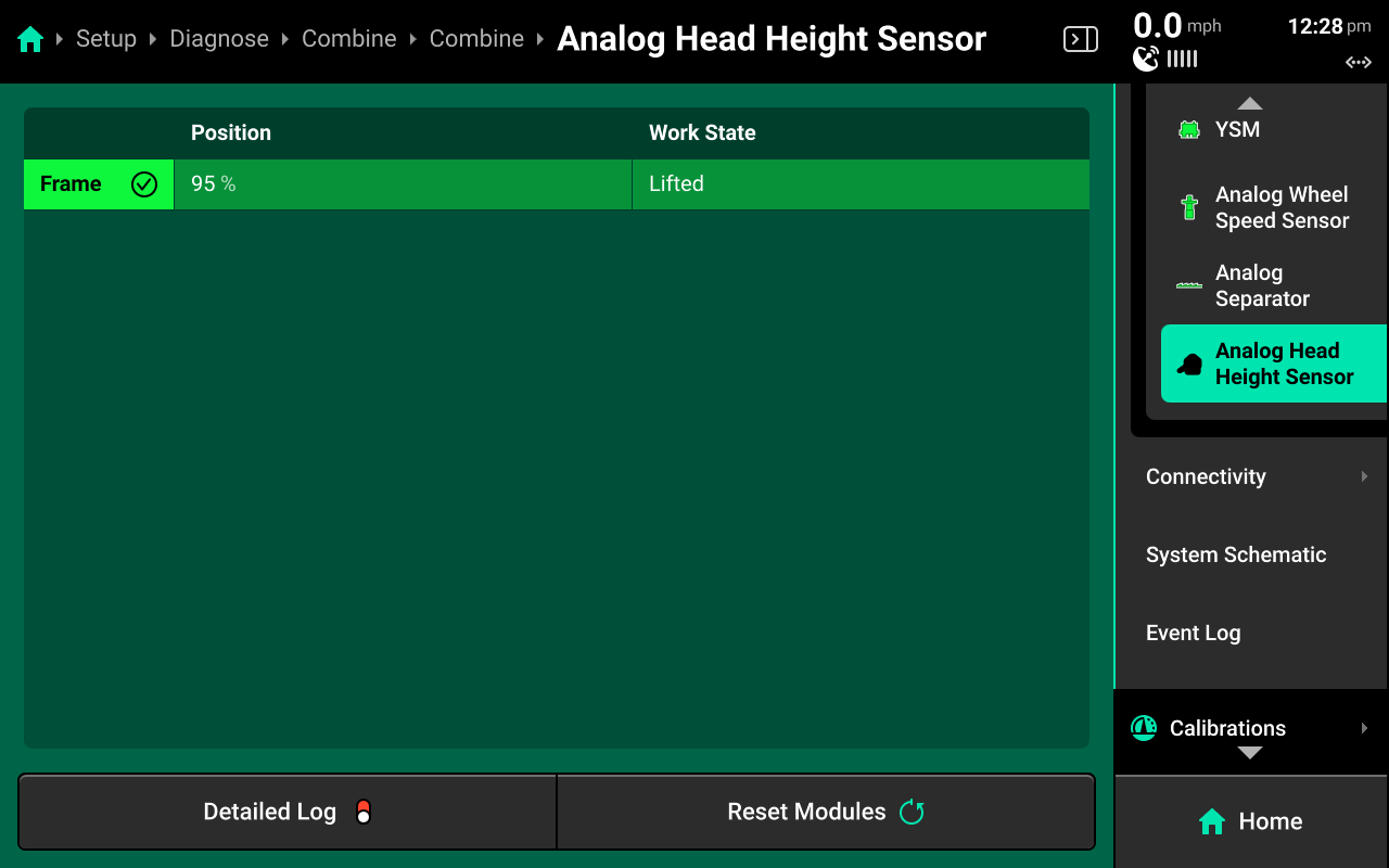
CAN / Analog Head Height Sensor
Select the head height sensor to view current position and corresponding work state for the sensor.
Other Diagnostics
Other diagnostics, such as Connectivity, System Schematic, and the Event Log are not specific to YieldSense and are not covered in this guide. For information on these diagnostics, see the 2025.1.x Gen 3 20|20 Operator's Guide.
YieldSight Installation
Use the following instructions to install the YieldSight system on a Fendt or Gleaner combine
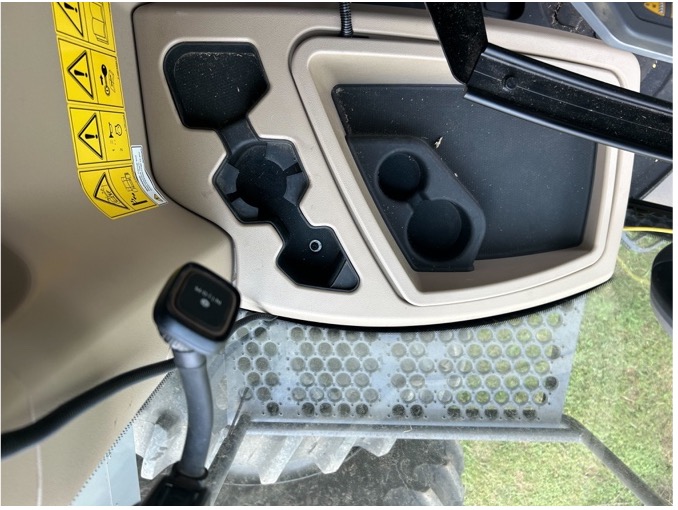
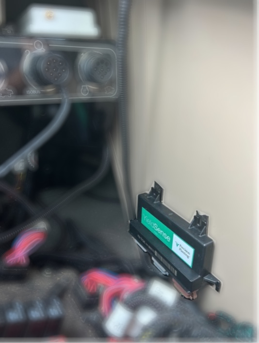
- Remove access panel for the fuse compartment.
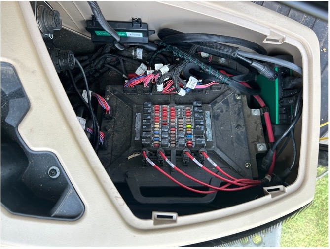
- Place the DBM in the compartment as pictured below.
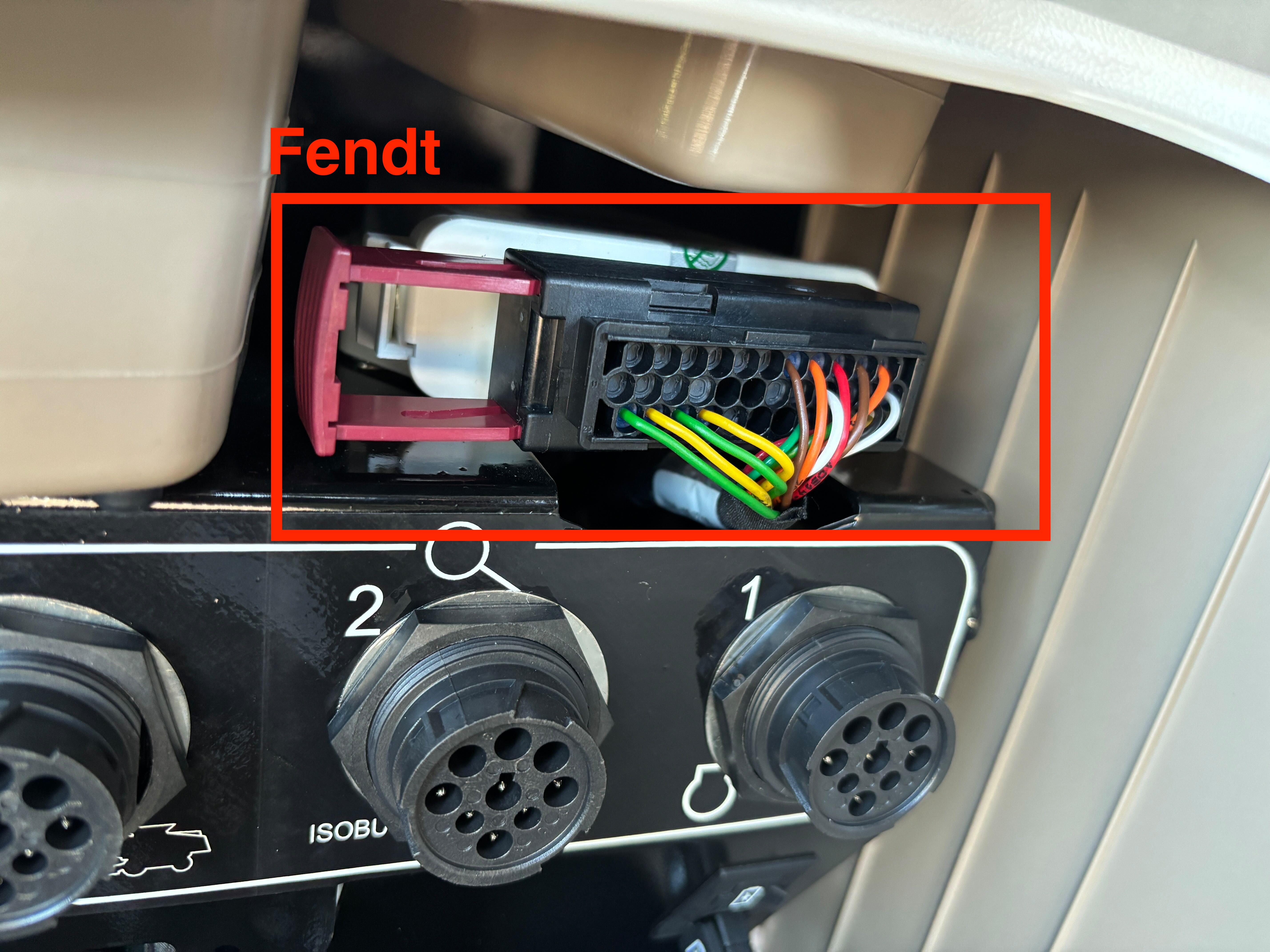
- Connect the GPS Output Harness to the Steering Controller (indicated in red) by removing the connector form the controller and inserting pins into the connector.
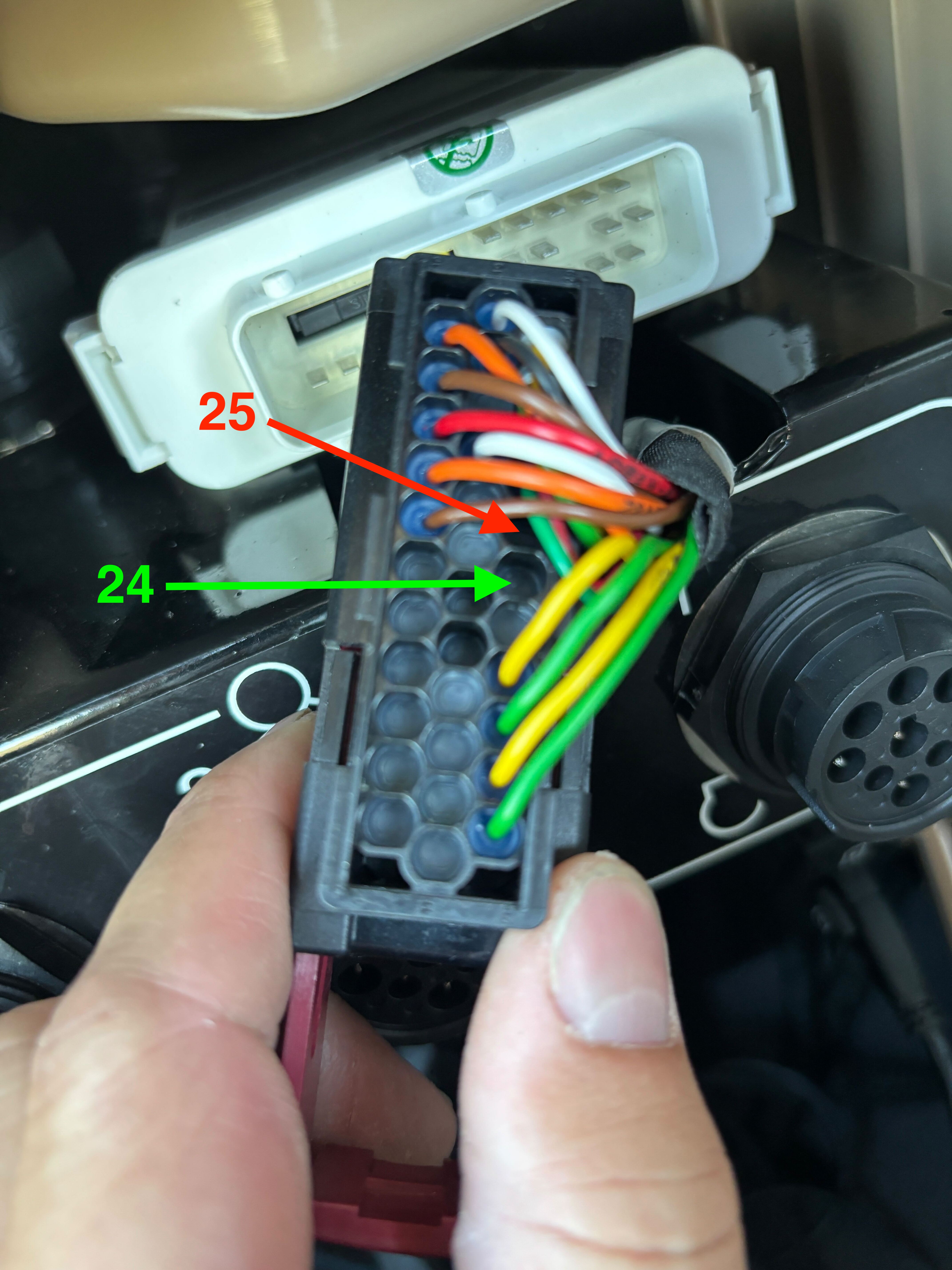
- Insert AMP pin 3 (Black) into position 24 on the Steering Controller.
- Insert AMP pin 2 (White) into position 25 on the Steering Controller.
For Gleaner S9 and 2019-2023 Ideal combines, the steering controller connection is located in the back of the cab. Remove the 3 bolts holding the panel in place to access the steering controller (pictured below).
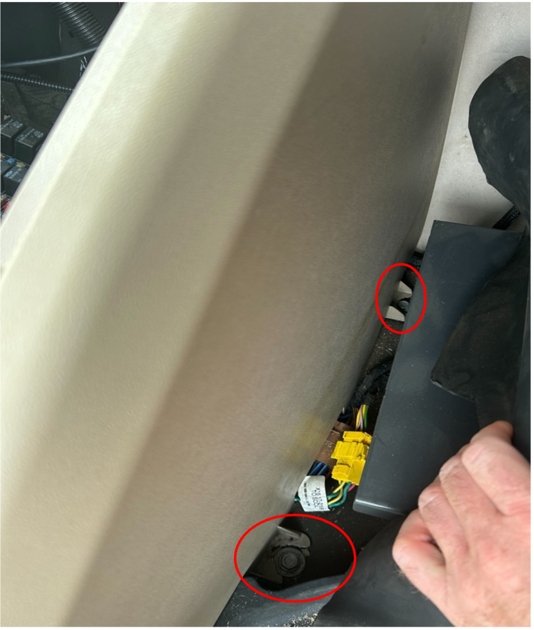
Then remove the 2x10mm bolts holding the controller in place to access the connector and install the GPS output harness.
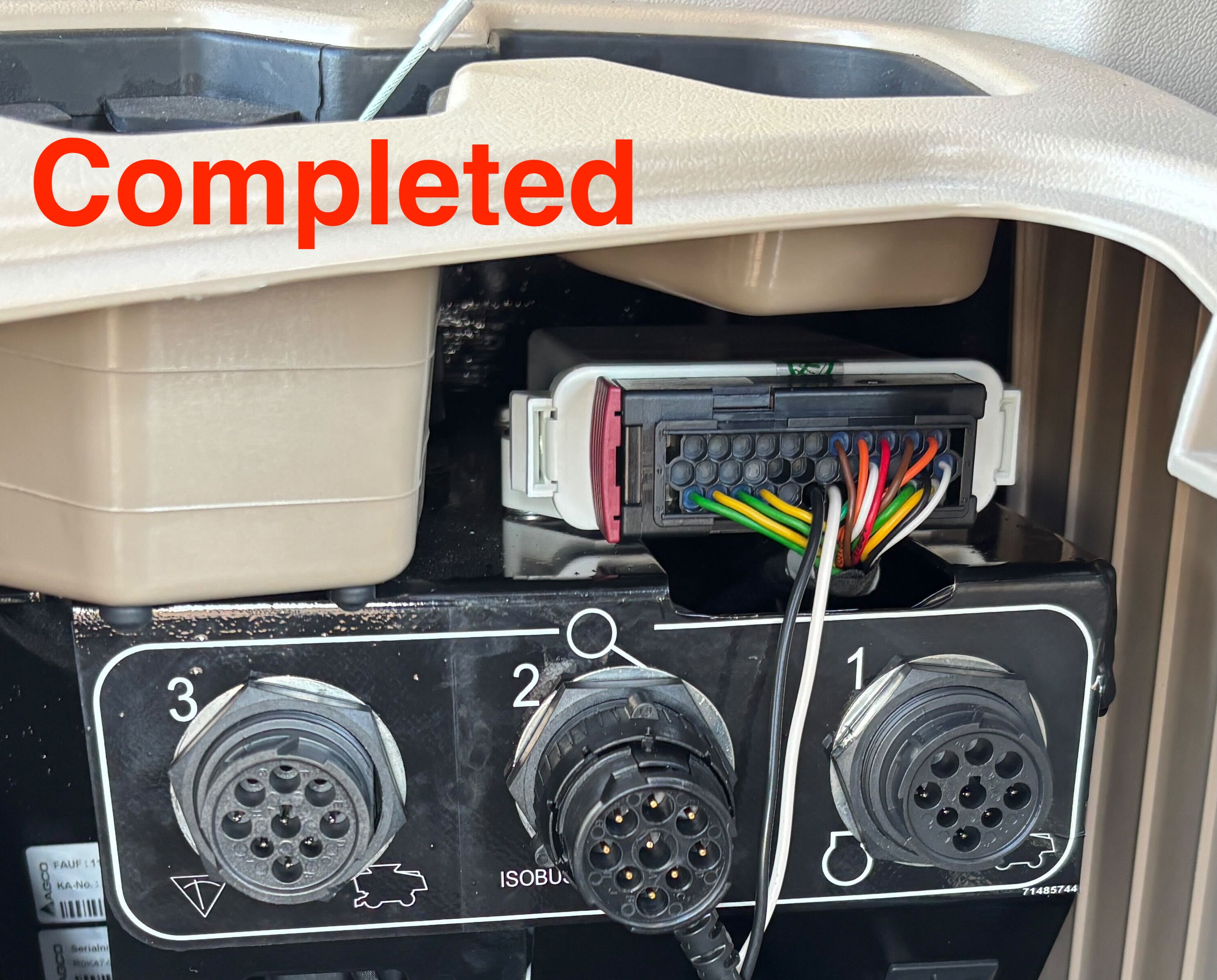
For 2024 Ideal combines, remove the harness connector and insert the pins into the connector.
-
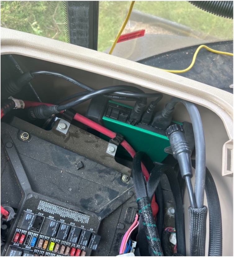
Connect the GPS adapter harness to the DBM speed harness.
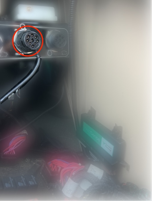
-
Install the CAN intercept Harness and connect to the OEM CAN port on the DBM.
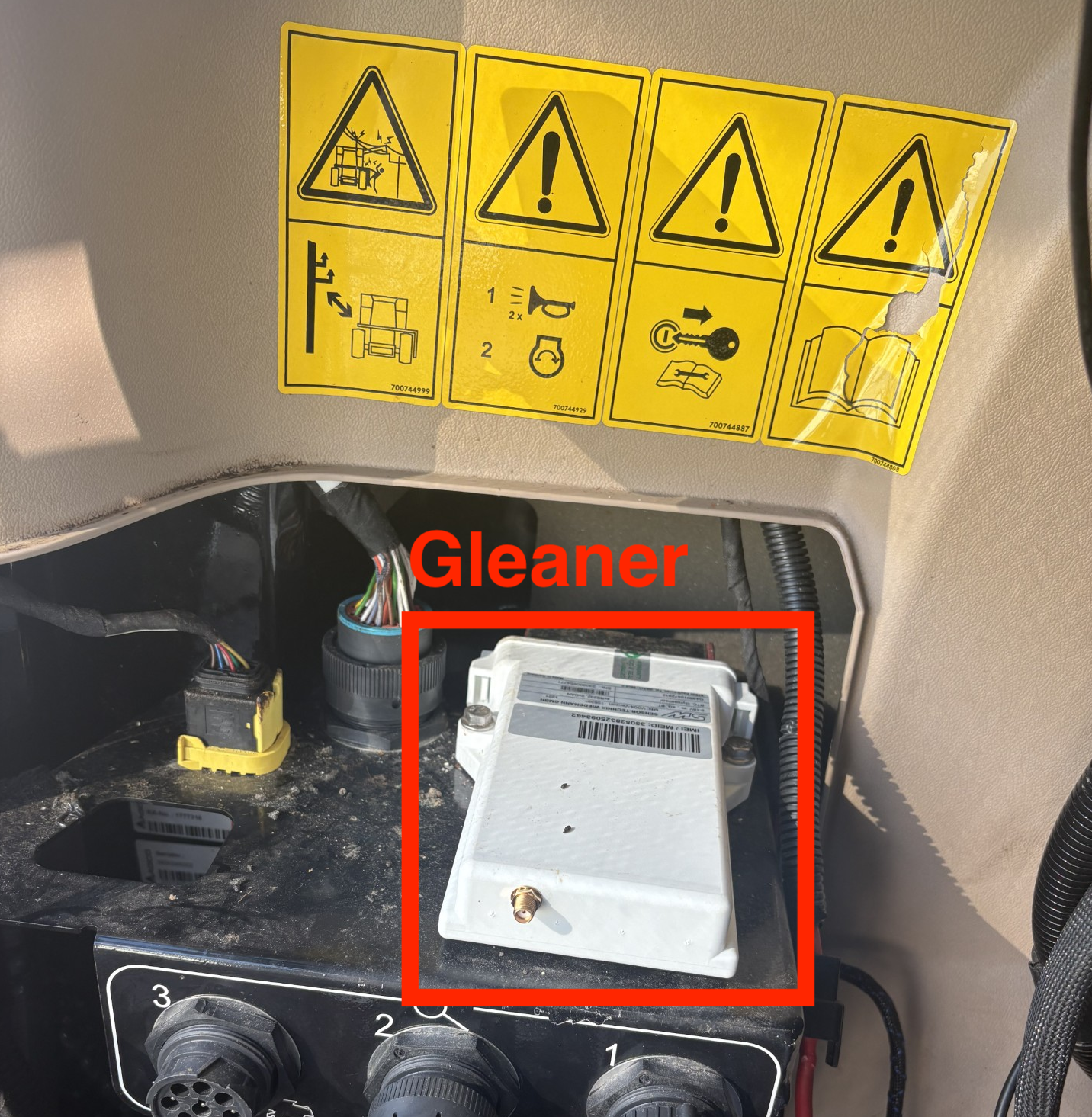
- Mount the YSM level on the panel with the decal facing the outside of the combine, then connect the YSM to the DBM.
-
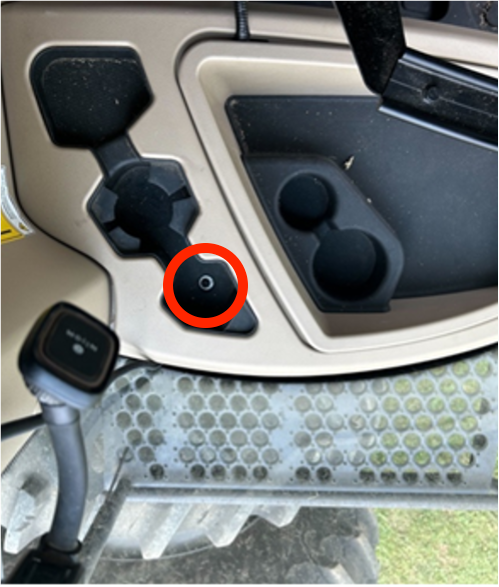
Connect the DBM Power Harness to the 9 pin factory cab plug.
-
Connect the Gen 3 20|20 display to the DBM.