SymphonyNozzle Operator's Guide
This guide is intended for use with limited release software 2025.1.x and its variants. Due to the nature of the limited release software update process, screenshots and descriptions provided in this guide may differ from the current version. Updates are made to this guide as often as possible. To download the most recent version of Gen 3 software, visit 2020.ag
Contents
This guide is intended for use with limited release software 2025.1.x and its variants. Due to the nature of the limited release software update process, screenshots and descriptions provided in this guide may differ from the current version. Updates are made to this guide as often as possible.
- SymphonyNozzle Requirements
- Equipment Setup
- System Setup
- Calibration
- Operation
- Diagnose
- Error Codes
- Appendix A - Swath Sensor Inputs
SymphonyNozzle Requirements
Hardware requirements for SymphonyNozzle:
- PWM pump control or Flow Requlating Valve product control
- Not compatible with hydraulic servo type valves
- Boom Diameter
- 1" Boom
- Standard Flow or High Flow available
- 3/4" Boom
- 1" Boom
- Wet or Dry boom
- Self-propelled or Pull-behind type sprayers
- In order to use OEM master switch (typically on the joystick) or OEM section switches on the console, it is necessary to have a OEM Swath Harness
- Check Order Guide for current swath harness compatibility
- For pull-type sprayers, there is a foot switch kit available.
Equipment Setup
Overview
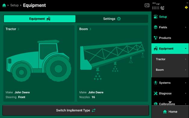
The Equipment menu is used to set up Tractor and Implement profiles. When navigating to the Equipment menu on a new 20|20, or after performing Delete All Data, the only equipment icon available by default will be Tractor.
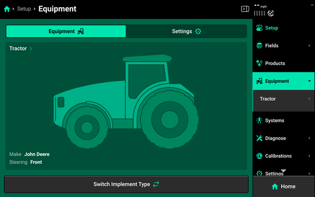
- To set up a Sprayer system, start by pressing the Switch Implement Type button to change between equipment modes. This will open a dialogue box that prompts the user to save the active tractor and implement if desired.
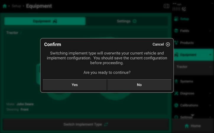
- If this is a first-time setup, press Yes. If there are any unsaved tractor or implement profiles active, press No, then navigate to any active profile pages and save the active configurations. For more information on saving/loading configurations, see Save/Load in this section.
-
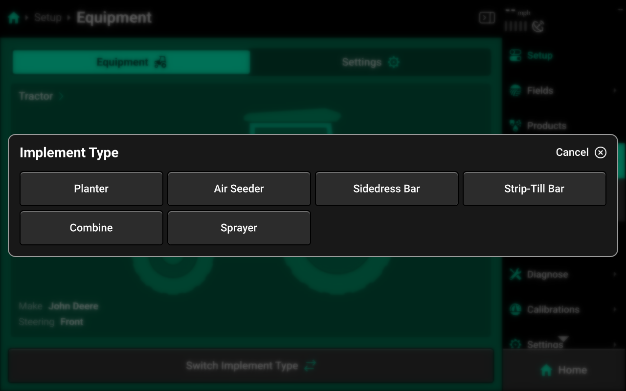
Press the desired implement type, then choose the appropriate subtype if necessary. When setting up your SymphonyNozzle system, you will have the option to choose between “Self-Propelled” and “Pull Behind” Sprayer options.
- Self Propelled Sprayer: Sprayer cab/boom combination.
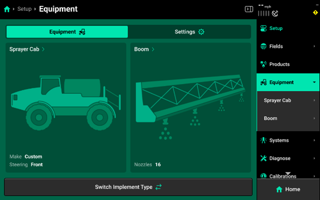
- Pull Behind Sprayer: Tractor/sprayer boom combination.
Sprayer Cab Setup
Use the Sprayer Cab setup card to configure the Model of sprayer cab and to configure your GPS measurements for proper control and mapping. See the GPS Setup section for more details on GPS Measurements.
Sprayer Cab Modules
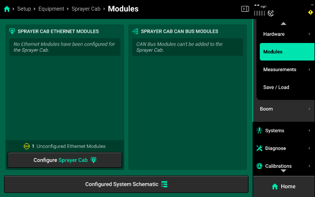
Use the Modules screen to set up Ethernet layout and serial numbers, and CAN module sequence and location. If the 20|20 is connected to Ethernet or CAN modules and all modules / harnesses are undamaged, then all detected but unconfigured modules will be shown under the left and right windows in the center as pictured.
-
Press Configure (Implement name / Cab name) in either window to begin setting up Ethernet or CAN modules.
-
If all Ethernet modules are detected correctly in the left window, press Add All Modules in the bottom of the right window on Step 1 to confirm and save auto-detected modules. To add only select modules, press each desired module in the left window, then press Add Selected Modules to confirm and save each highlighted module.
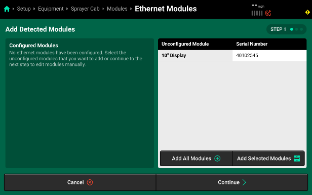
If Ethernet modules will be connected later, modules may be set up manually on Step 2 if desired. When using manual setup, it will be necessary to know the serial number of the manually added modules for the next step. Press Add Modules + in the right window and select the correct module from the popup.
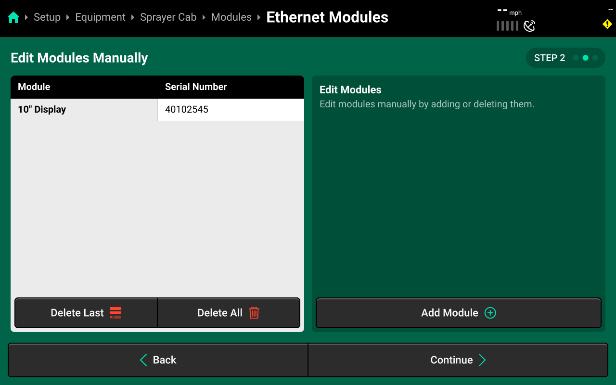
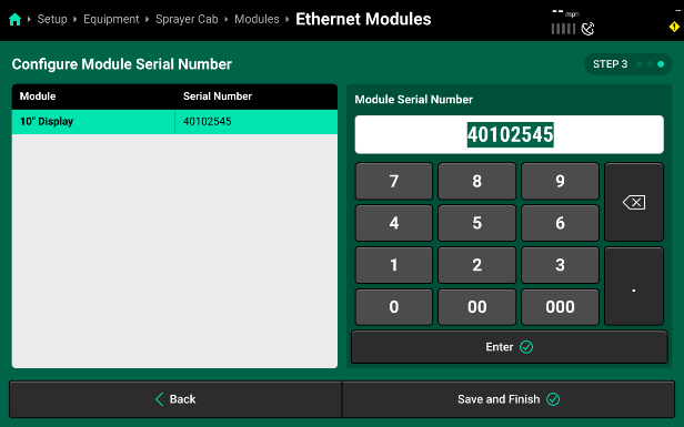
- Confirm or enter the correct serial number for each device on Step 3. Press Save and Finish to exit setup and return to Modules.
Sprayer Boom Setup
Use the Sprayer Boom setup card to configure the physical layout, size, and spacing of your sprayer boom equipment and nozzles.
Sprayer Boom Settings
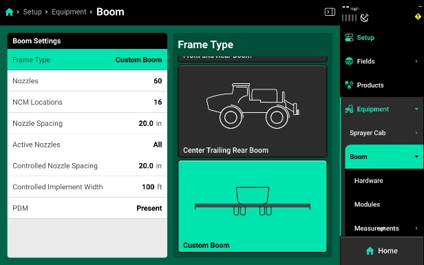
Selecting the Sprayer Boom card will open a page where you can define the specifics of your sprayer boom.
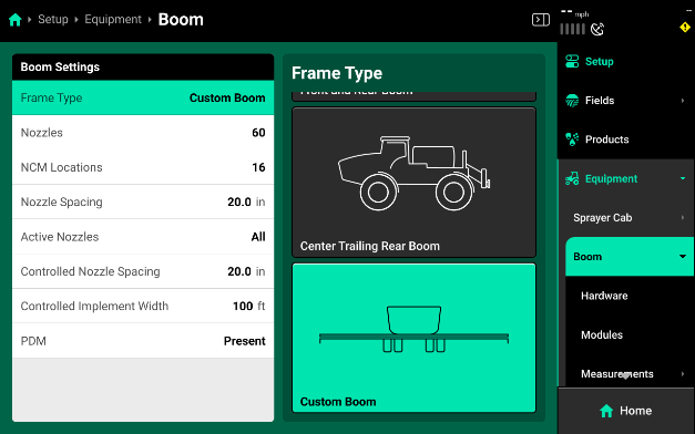
- Type: The Type options allow you to configure the physical layout of your boom style. It is recommended to use the CUSTOM option an all sprayer setups for the 2024 season. The custom option provides additional GPS options that allow for the most accurate boom setup. This will ensure proper swath control and GPS mapping.
- Nozzles: Use the Nozzles selection to input the total number of nozzles you are installing SymphonyNozzle control on.
- NCM Locations: Use this option to define the total number of Nozzle Control Modules (NCM) that are installed across the sprayer boom.
- Nozzle Spacing: Nozzle Spacing is used to define the physical nozzle spacing for your sprayer. This will be used to help calculate accurate swath.
- Active Nozzles: Active nozzles are used to configure which SymphonyNozzles are currently active and available to control your spray rate.
- Controlled Nozzle Spacing: Controlled Nozzle Spacing configures the 2020 to correctly output a rate specific to the active spacing. This is important to adjust when Active Nozzles have been changed.
- Controlled Sprayer Boom Width: Controlled Sprayer Boom Width is a calculation of Active Nozzles and Controlled Nozzle Spacing.
- PDM: PDM needs to be set to present on all SymphonyNozzle systems. This ensures proper turn rate compensation and map modeling as well as pump control options.
Please watch the “Sprayer Implement Setup” video to set up the custom GPS measurements for your specific sprayer. This video will walk you through how to configure each boom to correctly set up your GPS model for the sprayer boom and nozzle locations.
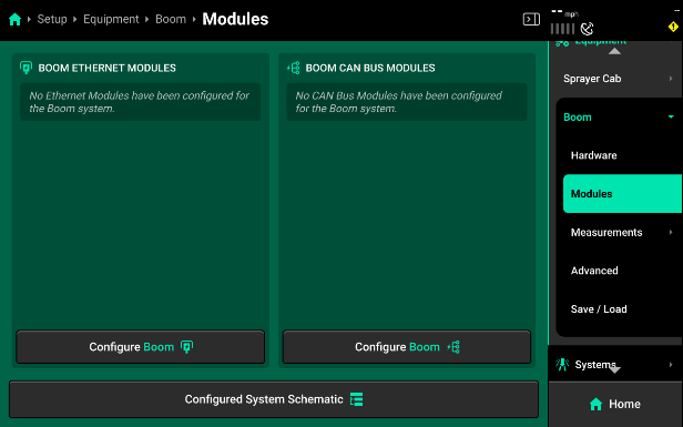
Sprayer Boom Modules
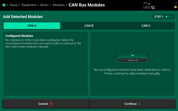
Press Configure Boom to open the Bus Devices screen. This screen allows the user to set up all other bus devices and CAN networks. No systems will function until bus devices and CAN networks have been set up in the 20|20 in the same configuration that those devices and networks are laid out physically on the implement.
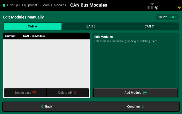
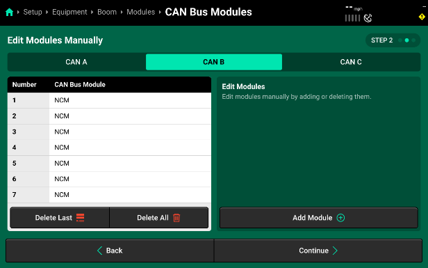
- If CAN modules will be connected later, modules may be set up manually on Step 2. Select Continue to proceed to the manual set up.
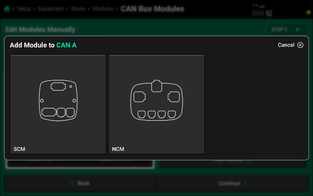
- Select the desired CAN network from the Bus list on the top of the screen, then press Add Modules + to add bus devices. Remember, CAN A is the middle boom section on a sprayer AND contains the Sprayer Control Module (SCM) inside the Sprayer PDM.
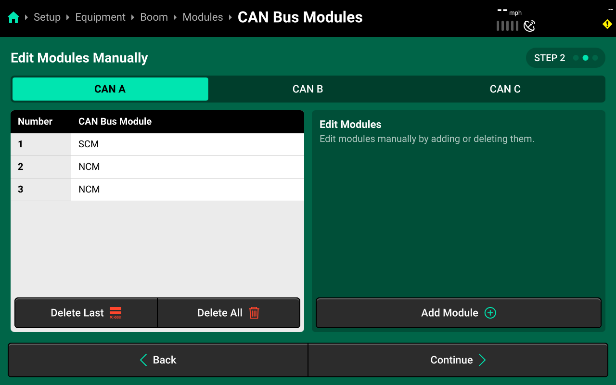
- Select the module you want to add and then use the pop-up to enter the number of selected bus devices that are installed in sequence on the selected CAN network. If another type of bus device is connected to the implement harnessing, enter a group size only up to the next type of bus device. On CAN A, a single SCM needs to be set up first.
- Continue by pressing “Add” again and then adding in the number of Nozzle Control Modules (NCM) that you have installed on CAN A. In this example, we have 2 NCMs added.
- Before hitting “Continue”, set up CAN B and then CAN C by selecting the CAN network from the Bus list on the left side of the screen. Follow the process above to “Add” modules to each network. On SymphonyNozzle, you will just have NCMs installed on CAN B and CAN C. In this example, we had 7 NCMs added to both CAN B and CAN C.
- After all CAN networks have been configured, press Continue to advance to module assignment. We will now define where each module on the three CAN Networks is located, in reference to the sprayer chassis and boom.
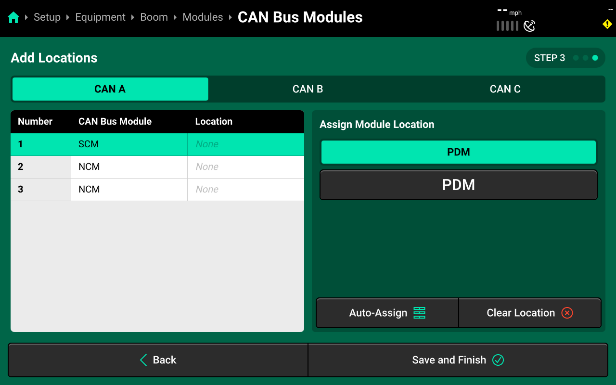
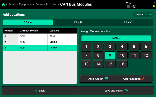
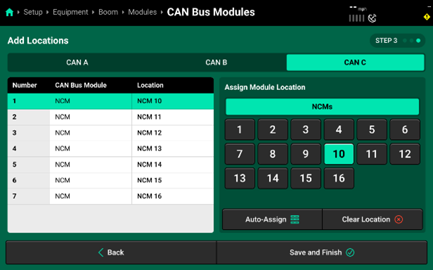
- Use the table under Assign Module to Location to view all available locations that may be assigned to a module. To properly assign the SCM on CAN A, select the “PDM” table and then “PDM” to assign the SCM inside the PDM. The location selection will be applied to the highlighted module in the table displayed in the center of the screen. Press Clear Selection to clear the location selection for the highlighted module only. Continue assigning locations to each module on CAN A by selecting the next module (Module 2|NCM) and then selecting “NCM Location” from the “Assign Module” table on the right. This location will define which NCM this is in reference to the total number of NCMs across all three CAN Networks on the Sprayer Boom. In our example (image below), the two NCMs on CAN A are assigned to the 8th and 9th NCM Locations.
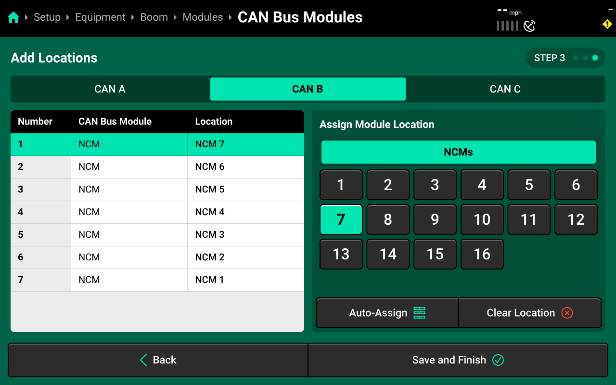
- Next, select CAN B from the Bus list on the left and step through assigning each NCM module to the physical location on the Sprayer Boom. Keep in mind that CAN B is ran from right to left across the left boom. As a result, the first NCM Module that the PDM is connected to is going to be assigned to the NCM Location that is right at the fold point of that left boom. Each module that is connected in series from the PDM out across the left boom will decrease in location number until you get to NCM Location number 1 out at the very tip of the left spray boom. In our example, the 7 NCMs on the left boom are assigned with NCM Module 1 getting assigned to NCM Location 7 and then each subsequent module on CAN B is assigned a location in descending order.
- CAN C will repeat this process, however, keep in mind that CAN C now connects from the PDM out to the right boom and each NCM Module will be assigned an NCM Location that is in ascending order. This is the opposite direction that CAN B was assigned. In this example, the 11 NCMs on CAN C are assigned location 10 to 16.
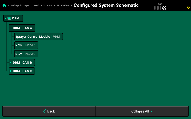
- Press Save and Continue to return to the Modules screen. If you now select the Configured System Schematic button at the bottom of the page, it will display all configured CAN networks. Press the dropdown arrow next to a CAN network to view the detailed schematic for that network. Scroll down on the table to view all modules or select another network .
Our example shows CAN A with its three connectors correlating with the Sprayer Control Module in the PDM Location, and then connector 2 and 3 with their NCMs assigned to NCM Location 8 and 9.
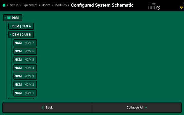
- Expanding CAN B shows all of the connectors on CAN B and their Modules and Location Assignments. Remember, since the CAN Jumper Harnesses start at the PDM, on the center boom section, and then connect out towards the left boom, running from right to left, the connector numbers end up being inverse compared to the physical NCM Locations. This allows the 20|20 to properly identify all of the NCMs in order of real-world locations and helps make module and nozzle identification easier for the operator when running the sprayer throughout the season. In our example, CAN B has 7 connectors correlating with 7 NCMs. The first connection from the PDM is assigned to NCM Location 7 and then each connection after that continues to decrease in number until NCM Location number 1 is reached at the far left sprayer boom tip.
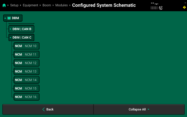
- Expanding CAN C shows all of the connectors on CAN C and their Modules and Location Assignments. Since the CAN Jumper Harnesses start at the PDM, on the center boom section, and then connect out towards the right boom, running from left to right, the connector numbers will increase incrementally along with NCM Locations. Again, this allows the 20|20 to properly identify all of the NCMs in order of real-world locations and helps make module and nozzle identification easier for the operator when running the sprayer throughout the season. In our example, CAN C has 7 connectors correlating with 7 NCMs. The first connection from the PDM is assigned to NCM Location 10 and then each connection after that continues to decrease in number until NCM Location number 16 is reached at the far-right sprayer boom tip.
Sprayer Cab Measurements
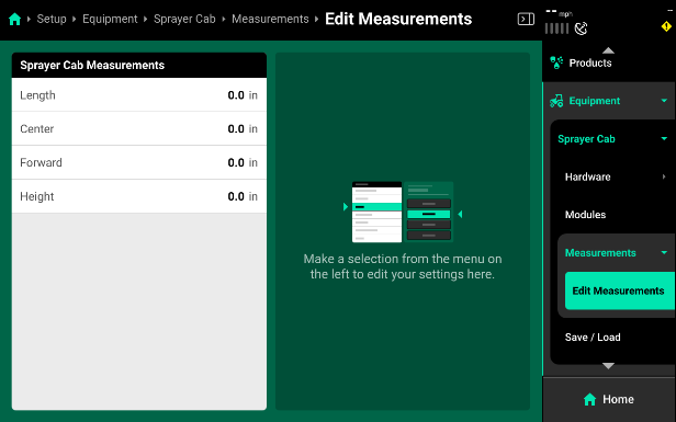
Sprayer Cab GPS measurements must also be setup prior to Spraying for accurate modeling and control of the sprayer. From the home screen select Systems – Equipment – Sprayer Cab – Measurements to enter measurements for the GPS.
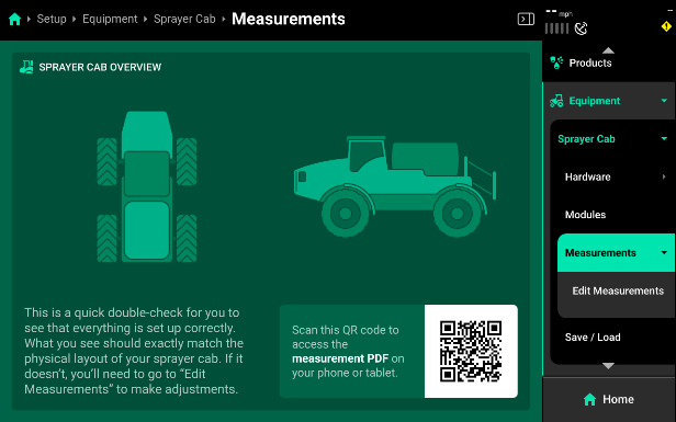
Some GPS systems do not output the location of the actual GPS globe. Verify the GPS output location with the GPS manufacturer.
- Length - Enter the distance from the center of the front axle to the center of the rear axle.
- Center - Measure the distance from the center line of the sprayer to the GPS output location. Then select if the GPS output location is to the left or right side of the tractor's center line.
- Forward - Measure the distance from the center of the rear axle to the center of the GPS antenna.
- Height - Measure the distance from the ground to the base of the GPS output location.
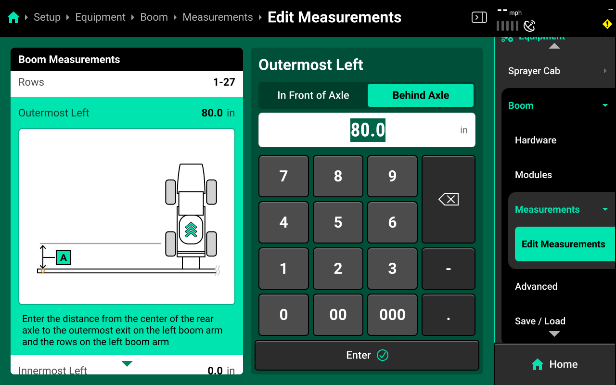
Boom Measurements
Due to the update frequency of all .1 software branches, the photos and description in this guide may differ from the version of software currently installed.
- Most sprayers should be set to “Custom Boom” to compensate for the tip of the booms being more forward than the center section.
- Set Each section to None before beginning to assign nozzles to a section.
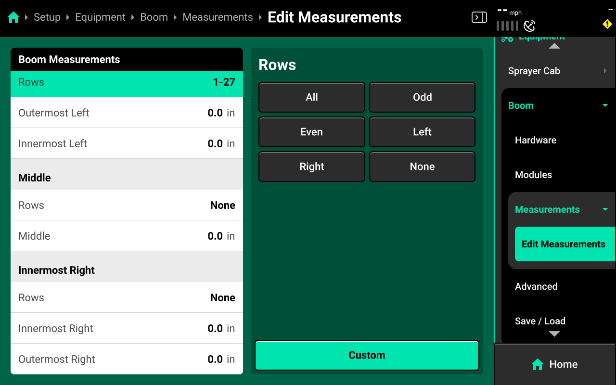
- Make sure that the In Front of Axle/ Behind Axle is toggled to the correct setting. For front boom sprayers it will be “In Front of Boom” and rear axles sprayers will be “Behind Axle.”
System Setup
General Setup
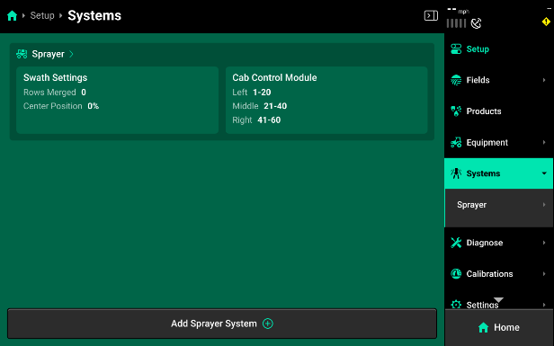
The main Sprayer tab (located in Setup>Systems>Sprayer) has all the settings and hardware that are used to define the sprayer as a whole. This is where the main Harnessing Setup is located and each individual control product can be setup and configured. Additionally, sprayer-wide control settings are located here; Swath Settings and Cab Control Module.
-
Swath Settings - This setting is used to configure the sprayer boom swath settings. Nozzles Merged allows the operator to tie several nozzles together on each end of the boom. This may be desirable when GPS accuracy is not exact and will allow for the merged nozzles to act like one larger section. The “Center Position” percentage gives the operator the ability to configure how this section of nozzles will behave when entering previous coverage. This percentage defaults to 0% as the middle of the nozzle section and allows for values from 100%, shifting the swath decision to the inside of the section, down to —100%, shifting the swath decision to the outside of the section.
-
Cab Control Module - This setting gives the operator the ability to configure which nozzles are controlled by which of the three Cab Control Module switches. Use the slider, or enter a percentage, to adjust your three sections.
-
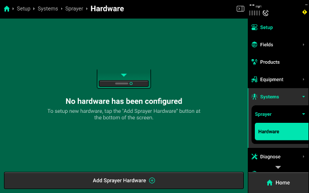
Add Hardware - Select Sprayer and then Hardware on the right side menu. Use the Add Sprayer Hardware option to setup up hardware that is assigned at a sprayer wide level.
- Implement Motion Sensor
The Implement Motion Sensor is a sensor installed inside every Sprayer PDM. This sensor is used in conjunction with GPS in order model the sprayer’s motion. This gives the system the ability for turn compensation, nozzle by nozzle rate and swath, as well as accurate mapping of data.
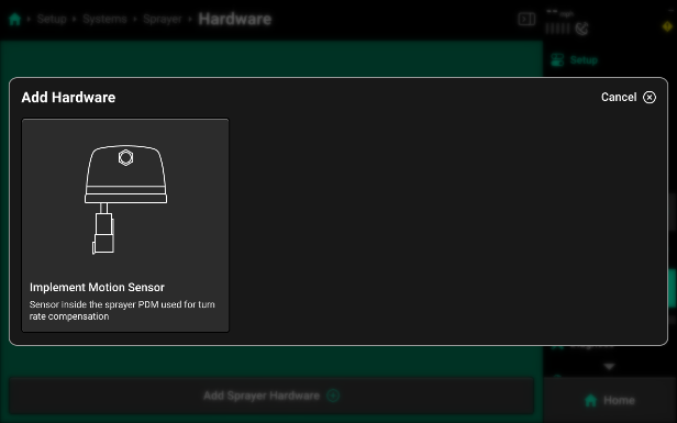
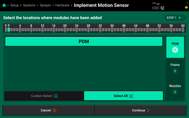
- To set up the Implement Motion Sensor, tap on “Add Sprayer Hardware” and then select “Implement Motion Sensor” from the list of hardware options.
- Next, assign the Implement Motion Sensor (IMS). Since it is installed in the PDM, select the module location of "PDM" and then press “Continue”.
- You will now see the Module Location and Settings. The settings for your Implement Motion Sensor (IMS) show it’s Gyro Zero Offset and if the sensor is currently enabled or not.
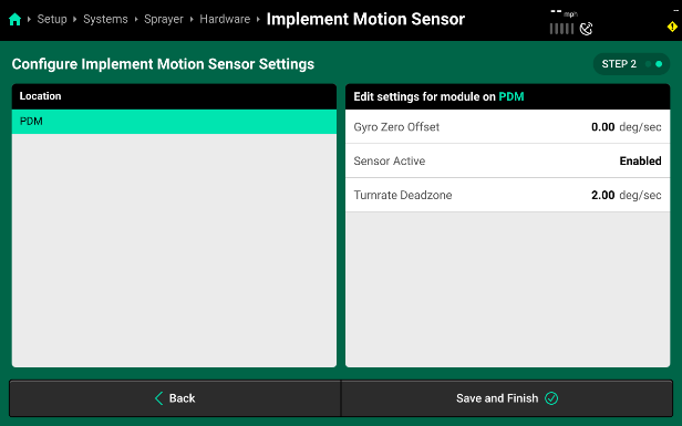
While the settings do show the current Gyro Zero Offset, you will need to navigate to the Calibrations Page in order to calibrate this offset properly. Do not enter a manual value.
Pressure
Sprayer Setup
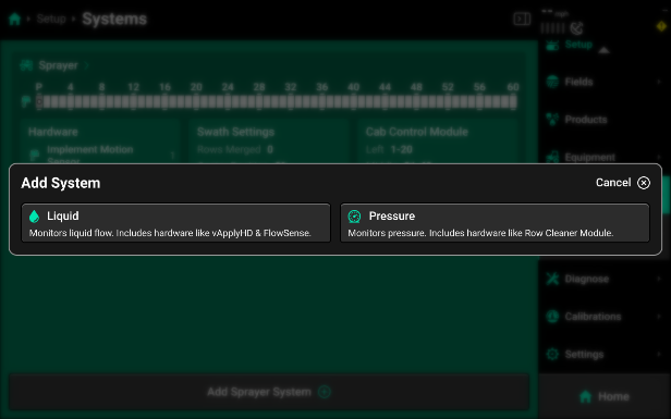
After setting up your “Harnessing” you can use the “Add Sprayer System” button on the bottom of the Sprayer systems screen to add your first control product.
- Pressure - The product setup that defines how SymphonyNozzle will control the pump for the desired operating pressure of the sprayer.
- Liquid - The product setup that defines how SymphonyNozzle will control the PWM nozzles to apply the desired application rates in the field.
Pressure Setup
Select “Add Sprayer System” and then select “Pressure” to start adding a pressure control system. The two system name defaults are either “Pressure” or selecting “Custom” to enter your own system name. This is the name that will be used for the Control Widgets and Metrics throughout the display. After selecting a system name you will be presented with the default pressure system setup page. You can now add the hardware that will interact and control the pressure system.
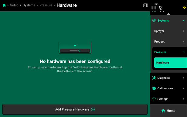
- Press "Add Pressure Hardware" to see a list of compatible hardware for your pressure system.
Set up only ONE of the hardware options listed below. Pressure systems can only operate if one hardware solution is in control.
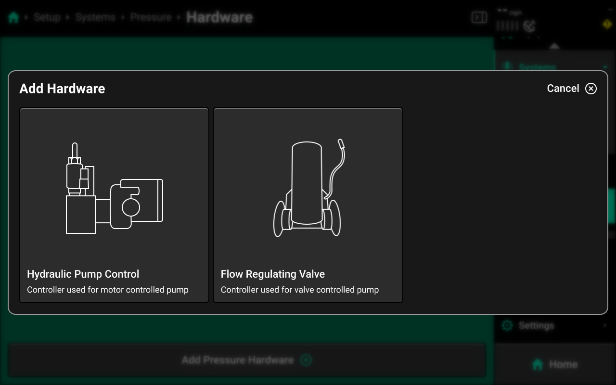
- Pump Control
- Hydraulic Pump Control - used to set up a pump that is controlled with a PWM valve. This will control the pump directly via hydraulic flow in order to maintain the selected pressure control set point in the field.
- Flow Regulating Valve - is used to set up a system that has a constant pump speed and regulates pump output with a butterfly style valve in order to maintain the selected pressure control set point in the field.
- Select the correct control style to then set up that hardware.
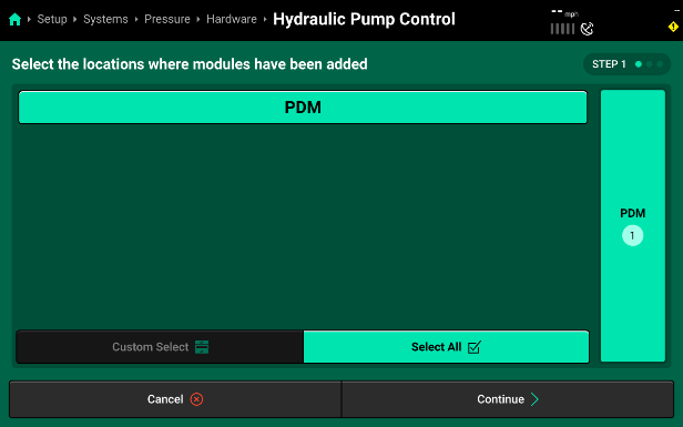
- Selecting a pump control hardware option will then bring you to a module setup screen. Select the location this module plugged in to. By default, the Sprayer Control Module (SCM), that you are using to control a PWM pump or Regulating Valve, is located inside the PDM and you will need to make sure to have PDM selected.
- Pressing “Continue” will bring you to the “Module Settings” page for the pump. First, assign the module to the nozzles that it is controlling product for (SymphonyNozzle pump control should have all nozzles selected). Then you can use the “Settings” menu on the right to set up pump control defaults.
Pump Control Settings
- Pressure Hold - This value sets the pressure at which the system will maintain when you are not actively spraying but still have the pressure control system enabled.
- Pressure Offset - This value defines the zero point for the pressure sensors used in the SymphonyNozzle control.
Pressure Offset should not be changed unless instructed by Product Support.
- Pressure Scale - This value sets the scale of the pressure sensors used in the SymphonyNozzle system.
Pressure Scale should not be changed unless instructed by Product Support.
- Pump Control Gain - This is the gain for how fast or slow the pump reacts to commanded changes. Adjustments should be made in 0.1 increments.
- Increasing the gain will make the pump react with ‘faster’ commands.
- Decreasing the number will result in the pump making ‘slower’ commands.
- Nozzle Control Gain - This is the gain for how fast or slow the PWM Nozzles react to commanded changes. Adjustments should be made in 0.1 increments.
- Increasing the gain will make the nozzles react with ‘faster’ commands.
- Decreasing the number will result in the pump making ‘slower’ commands.
Nozzle Gain should not be changed unless directed by Product Support.
- Pump PWM Frequency - This number sets the frequency the Sprayer Control Module (SCM) will control the PWM Valve on your pump.
- Maximum PWM - This sets the maximum PWM percent that the system will commend for pump control.
- Minimum PWM - This sets the minimum PWM percent that the system will commend for pump control.
Flow Regulating valve Settings
- Pressure Hold - This value sets the pressure at which the system will maintain when you are not actively spraying but still have the pressure control system enabled.
- Pressure Offset - This value defines the zero point for the pressure sensors used in the SymphonyNozzle control.
Pressure Offset should not be changed unless directed by Product Support.
- Pressure Scale - This value sets the scale of the pressure sensors used in the SymphonyNozzle system.
Pressure Scale should not be changed unless directed by Product Support.
- Nozzle Control Gain - This is the gain for how fast or slow the PWM Nozzles react to commanded changes. Adjustments should be made in 0.1 increments.
- Increasing the gain will make the nozzles react with ‘faster’ commands.
- decreasing the gain will result in the pump making ‘slower’ commands.
Nozzle Gain should not be changed unless directed by Product Support.
- Pump Valve Braking Point - Percent error in flow from target above which valve moves at full speed.
- If flow has large oscillations, increase braking point.
- If control seems slow to reach target, decrease braking point.
- Pump Valve Deadband - Percent error in flow from target below which valve does not move.
- If flow seems to have small oscillations around target, increase deadband.
- If flow seems to stabilize slightly above or below target, decrease deadband.
Liquid
Select “Add Sprayer System” and then select “Liquid” to start adding a liquid control system. The two system name defaults are either “Product” or selecting “Custom” to enter your own system name. This is the name that will be used for the Control Widgets and Metrics throughout the display. After selecting a system name you will be presented with the default liquid system setup page. You can now add the hardware that will interact and control the liquid system.
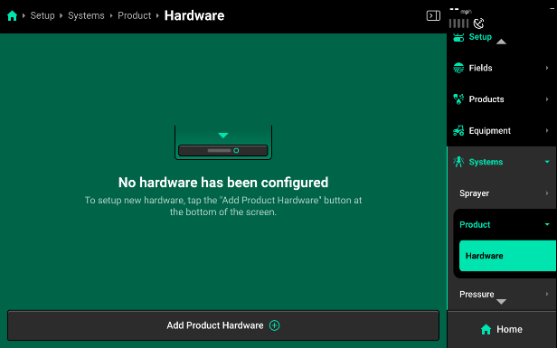
Press Add Product Hardware to see a list of compatible hardware for your product system.
![]()
Now add the hardware you need to set up
Sprayer Control Module [SCM] Flow Meter
Used to set up the flow meter that will provide boom-wide flow feedback for SymphonyNozzle System. A flow meter is needed for accurate PWM nozzle control.
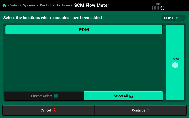
- Selecting “SCM Flow Meter” will walk you through setting up the SCM Flow Meter. First, assign the module location the flow meter is plugged in at. On SymphonyNozzle systems, the flow meter plugs in to the SCM at the PDM location.
- Pressing “Continue” will bring you to the “Module Settings” page for the flow meter. Assign the flow meter to the nozzles that it is monitoring product for (SymphonyNozzle flow meter systems should have all nozzles selected). Then you can use the “Settings” menu on the right to set up flow meter defaults.
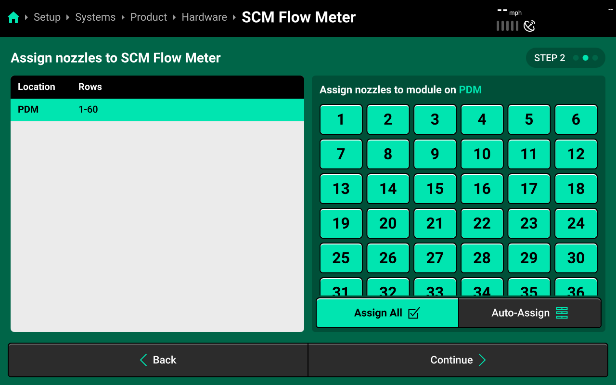
- Press continue again to set the flow meter settings.
SCM Flow Meter Settings
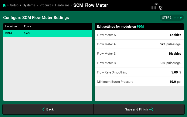
- Flow Meter A
- Make Sure your flow meter is enabled.
- Flow Meter A (pulses/gal) - This value defines the number of pulses per gallon that your flow meter is calibrated for.
Refer to your OEM flow meter tag, manual, or the OEM monitor to find out what your pulses are.
- Flow Meter B - Only needed if your sprayer is a high flow style sprayer that utilizes two flow meters.
- Enable or disable this secondary flow meter here.
- Flow Meter B (pulses/gal) - This value defines the number of pulses per gallon that your flow meter is calibrated for.
Refer to your OEM flow meter tag, manual, or the OEM monitor to find out what your pulses are.
- Flow Rate Smoothing - This value sets the percentage of smoothing that you want to allow on the home screen flow rate metric. Increasing this number will result in less variation displayed on the Liquid Rate Metric.
- Minimum Boom Pressure - This setting is only used when the PWM Nozzles have all been disabled and the SymphonyNozzle system is operating as a flow only system. Minimum Boom Pressure will be the lowest pressure the flow system will operate at.
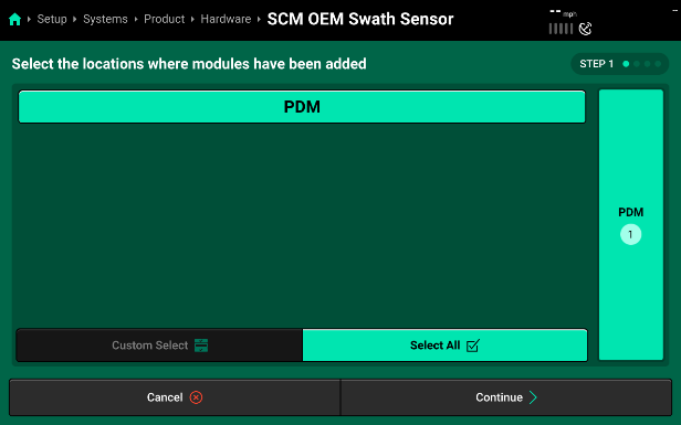
Sprayer Control Module [SCM] OEM Swath Sensor
Used to set up an OEM Swath Harness. This harness taps into the signal of the in-cab OEM swath switches and allows SymphonyNozzle to see when the operator turns off a manual swath valve. This harness is set up in this step to assign the PWM Nozzles you want to also shut off when a specific OEM Swath switch is turned off.
- Select SCM OEM Swath Sensor to walk through the OEM Swath Sensor Input setup.
- First, assign the location the OEM Swath Sensor Harness is plugged in at. On SymphonyNozzle systems, this harness plugs in to the SCM at the PDM location.
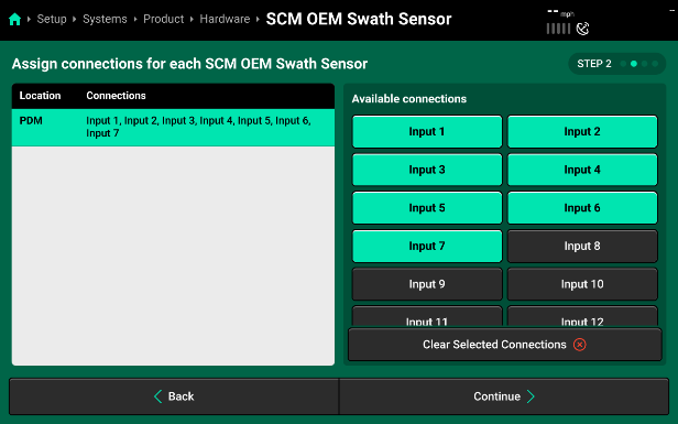
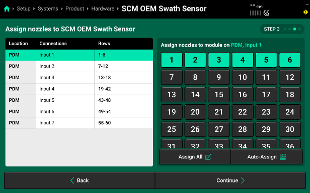
- Pressing “Continue” will bring you to the “Module Connections” page for the harness. Select the Input Connections your harness uses to match the OEM Cab Swath Valve switches to the input connections on the SCM OEM Swath Sensor Harness. Refer to Appendix A find Make and Model charts for your specific harness.
- The last step is defining which PWM Nozzles should be assigned to turn on/off with the OEM Input Connection. The nozzles should match the number of nozzles on the physical section supply valve boom section.
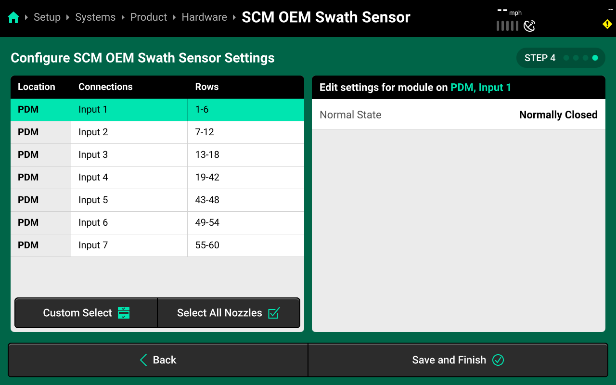
- The last step is setting the “Normal” state of the valves. If the system is at 0V with the valves closed then you will leave it on the default of “Normally Closed”. If the system has a 12v signal when the valve is closed, you will want to select “Normally Open. Make sure to “Select All Nozzles” before making a change so that it applies sprayer wide.
Nozzle Solenoid
Used to set up PWM Nozzles for SymphonyNozzle.
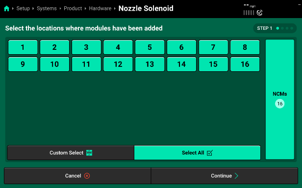
- Selecting “Nozzle Solenoid” will walk you through setting up all of the PWM Nozzle Solenoids on the SymphonyNozzle system. First, select all the Nozzle Control Modules that have PWM Nozzles plugged in. On SymphonyNozzle systems, all NCMs should be in use and have at least one PWM nozzle in use.
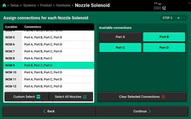
- Pressing “Continue” will bring you to the “Module Connections” page where you will select all of the connection ports in use on each NCM. Make sure to verify ALL NCM connections by selecting each NCM from the left-hand list.
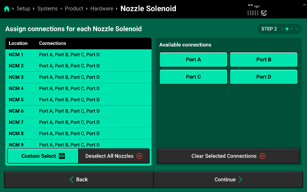
- Once all ports are assigned to every NCM, go through and take off any ports that do not have a nozzle connected.
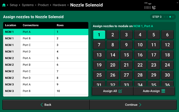
- Press “Continue” to define which port on each NCM locations corresponds to which PWM nozzle on the sprayer boom. If you set up the Module Connections page correctly, you can hit “Auto-Assign” and the system will automatically assign each port a nozzle location in order.
- Select “Continue” to move to the last and final step. On step 4 you will be able to change Nozzle Solenoid settings. You will want to make sure to “Select All Nozzles” before changing any of these settings.
Nozzle Solenoid Settings
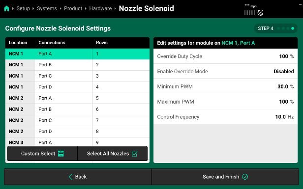
Each setting is specific to the Nozzle Location you have selected in light green on the left of the page.
- Override Duty Cycle - This duty cycle percent defines the duty cycle that this specific nozzle will perform if the Enable Override Mode is Enabled.
- Minimum PWM - This value is the minimum Duty Cycle percent that this specific Nozzle can control to.
- Maximum PWM - This value is the maximum Duty Cycle percent that this specific Nozzle can control to.
- Control Frequency - This is the frequency that this specific PWM Nozzle will control at.
Calibration
This section is where all of the Calibrations that must be completed for SymphonyNozzle
Implement Motion Sensor [IMS] Accelerometer Calibration
- Select the IMS Accelerometer Calibration to begin. Follow the “Prepare to Calibrate” prompt screen.
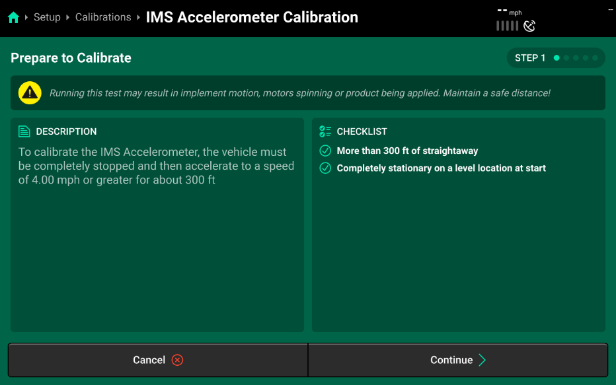
- This Calibration will require you to completely stop your equipment and then accelerate to a speed of 4 mph or greater.
- Make sure you have more than 300 ft of straightaway and are completely stationary and level before you begin this test.
- Press “Continue” when you are ready to proceed.
- Step 1 instructs you to make sure you are at a complete stop for 5 seconds before then pressing continue.
- This page will present a readout of your accelerometer:
- Supply - Suply Voltage should be above 12V.
- Turn Rate - Turn rate should be 0.0.
- Acceleration - Acceleration should be close to zero. This sensor is very precise and it’s not uncommon to see some values here due to implement vibrations. Ex. This sprayer was showing –0.006 when stationary. Press Continue when ready.
- This page will present a readout of your accelerometer:
- Step 2 will give instructions to ensure you have 300 ft of straightaway and will be able to reach a speed of 4mph or greater.
- Press Continue when you are ready
- Step 3 will give instructions to accelerate to a speed of 4mph or greater.
- Press Continue after you have reached a speed of greater than 4mph.
- Step 1 instructs you to make sure you are at a complete stop for 5 seconds before then pressing continue.
- Calibration complete - here is the summary page
- Verify the calibration
- Accelerate and slow down while watching the acceleration number on this screen.
- Accelerating: positive number
- Slowing down: negative number
- Accelerate and slow down while watching the acceleration number on this screen.
- Press Done to complete.
Implement Motion Sensor [IMS] Gyro Calibration
- Select the IMS Gyro Calibration to begin. Follow the “Prepare to Calibrate” prompt screen.
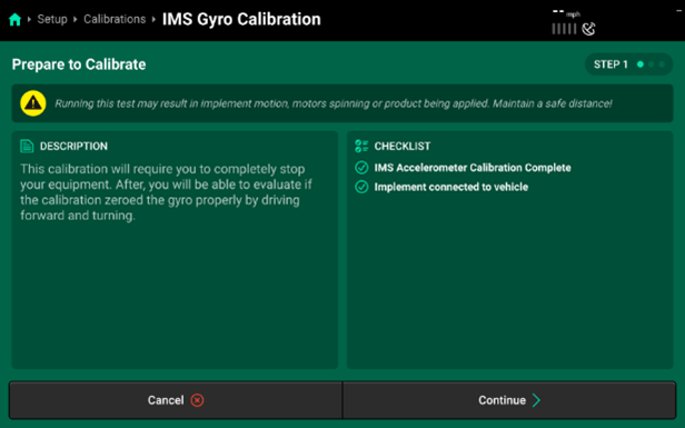
- This Calibration will require you to completely stop your equipment, prior to starting the calibration process.
- You will also need to have the implement connected to the vehicle (this is more focused on pull-type sprayers or other implements like planters).
- Press “Continue” to begin.
- Step 1 will require you to be completely stopped. Press continue after you have come to a complete stop. This will set the expected “zero” for your Gyro.
- You will now be presented with a Summary Page. Driving your vehicle and turning should now provide you with a “Turn Rate” value. You will also see “Acceleration” values since you have already calibrated the Accelerometer in the processes before.
- Press “Done” to finalize your IMS Gyro Calibration.
GPS Offset Check
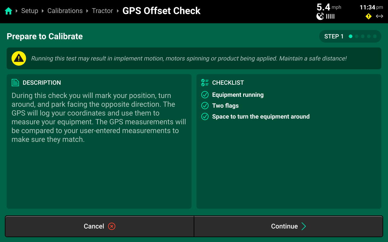
Run through the calibration wizard to perform the offset check following the on-screen instructions. Ensure that the application points / seed exits are even with the placed markers on step 1 and step 4.
This test may be easier to perform with a spotter to determine that the application points / seed exits are even with the placed markers.
Resulting differences of less than 12 inches are recommended, but best control will be experienced with differences as close to 0 as possible. Higher differences will result in less accurate swath timing.
Precision Planting Product Support recommends to repeat this test and / or remeasure implement dimensions to achieve more accurate results before using start / stop timings and application offsets to fine-tune control. Support also recommends to perform this check at every season start.
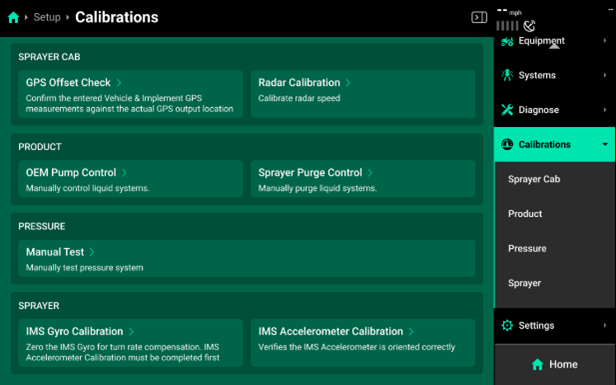
OEM Pump Control
This allows the OEM system to take control of the pump when running an automated rinse cycle or when using the load computer outside of the cab.
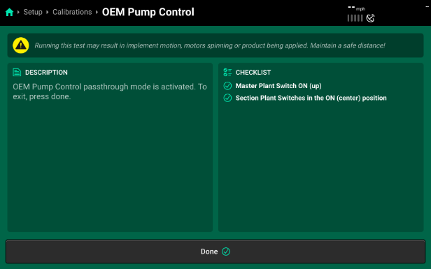
- Access this control from the calibrations page or a control widget can be added to the home screen.

For this to be activated, Product must remain “Enabled” and you must follow the checklist provided on the right side of the screen.
To ensure smooth transition, shut the pump off using the CCM switches before switching to this control mode.
Sprayer Purge
This allows the nozzles to open and allow product to flow through without pressure or speed to drain the boom, relieve pressure off the boom, or complete an air-purge.
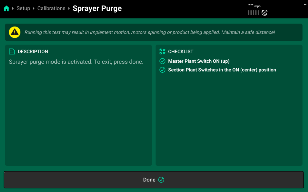
- Access this control from the calibrations page or a control widget can be added to the home screen.

For this to be activated, Product must remain “Enabled” and the checklist provided on the right side of the screen must be complete.
Operation
Tank Mixes
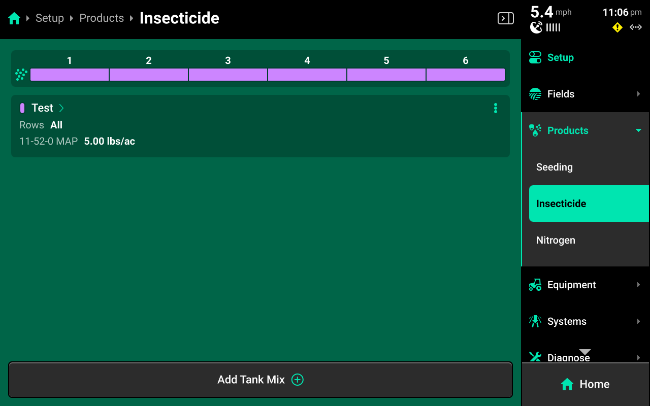
Press any of the liquid or granular systems under Products to add, delete, or modify tank mixes. A table of all tank mixes for the selected system is displayed in the center. Press Add Tank Mix + and enter the desired name for the tank mix. A new tank mix will then be displayed in the table.
Press on any tank mix in the table to set active rows for that mix and add granular or liquid products to it.
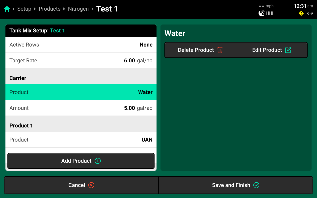
If setting up a liquid tank mix with a carrier, the carrier must be added first. Changing Target Rate on this screen will increase only the amount of carrier. See the above image for an example. The system will continue to apply the rate commended in the Control Screen, regardless of tank mix ratio.
The 20|20 will not indicate on the map when a new product is added to an existing tank mix. To track changes to a mix on the map, set up a new mix instead of editing an existing mix.
Field Setup
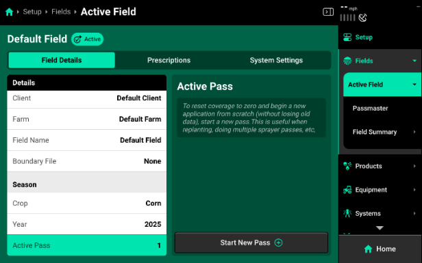
Press the active field on the Fields Landing Screen, or press Active Field under Fields in the Navigation Menu to navigate to the Active Field screen. Use this screen to access all options from the Field Setup screen with the Navigation Menu still visible.
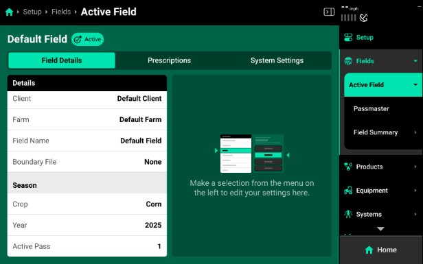
Active Pass - When going back to the same field to make another application you will need to start a new pass to clear coverage and start a new map layer. Select “Start New Pass” at the bottom right of the screen.
Pump Start Up
To start the pump after getting the systems setup.
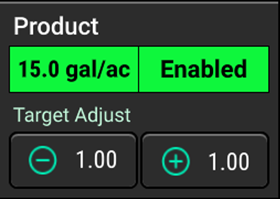
- Product widget must be Enabled with a rate input.
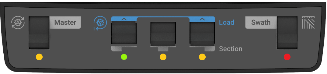
- Either Master switch or one of the three section switches in the ON position. (indicated by a green LED light)
When the pump is running and the system is not applying, Pressure will default to the Pressure Hold that was set in the Hydraulic Pump Control settings.
Spraying - PWM Mode
PWM mode will control the pump to maintain system pressure set in the Pressure control widget and then it will use the nozzles to control the target rate set in the Product Control widget.
- Enable Product System - Set a target rate
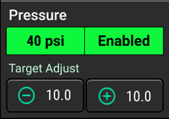
- Enable Pressure system - Set a target pressure
- Master switch and at least one of the three section switches in the ON position. (indicated by a green LED light*)
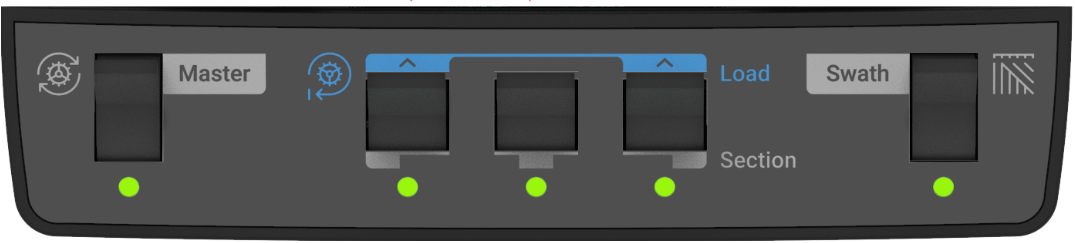
In order to spray with the whole boom, all 3 swath switches must be in the ON position. (indicated by a green LED light)
- To start spraying, the 20|20 must see speed.
- Can be GPS, Radar, or simulated speed by engaging Quick Start.
Spraying - Flow Only Mode
“Flow Only Mode” will be used in applications where a PWM compatible application isn’t being used. This will open the nozzles to 100% DC and the system will control the pump to manage the target flow rate. Pressure will vary to maintain target rate.
Possible uses might be for Streamer bars, Side-dress application, Nozzle Drops
- On the home screen set the Product control system to Enabled
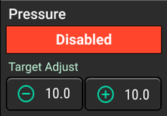
- Set the pressure control system to Disabled.
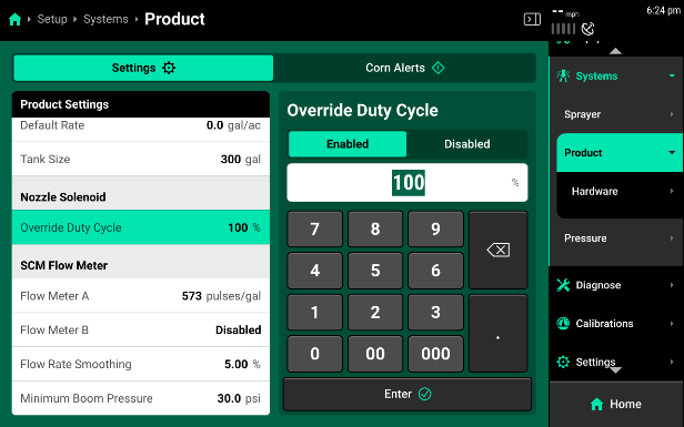
- Go to Setup>Systems>Product, scroll down to Override Nozzle Duty Cycle, select Enabled, set to 100%.
Testing After Setup
To start the pump after getting the systems setup.
- Product widget must be Enabled with a rate input
- Either Master switch or one of the three section switches in the ON position. (indicated by a green LED light)
- When pump is running and system is not applying, Pressure will default to Pressure Hold which was set in the Hydraulic Pump Control Setttings.
Once the pump is running:
- enable both the Product and Pressure systems
- Ensure target values are set for Rate and Pressure
- On CCM, set Master Switch and at least one of the three Section Switches to the ON position (green LED light).
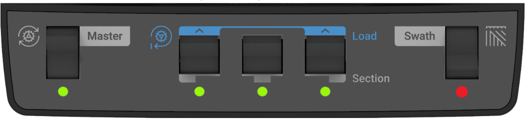
- To test while sprayer is sitting still, set Swath Switch to off position (red LED light)
For the nozzles to spray the 20|20 needs to have a speed. That speed can be GPS, Radar, or use a simulated speed by engaging Quick Start.
Using Quick Start
Quick Start on a sprayer will allow the machine to start spraying when it is stopped. This will allow Operators to check systems after setup, prime the boom, rinse the boom, or when applying out of corners to avoid a delay in application with no wheel speed sensor or radar. A Quick Start widget is available for the homescreen.

Always test the system with water and a flushed boom.
The start delay, timeout, and simulated speed can all be adjusted to the operators’ preferences. To test the system set a speed like what will be ran in field conditions.
Quick Start Settings can be accessed through Setup> Equipment> Settings tab at the top of the page
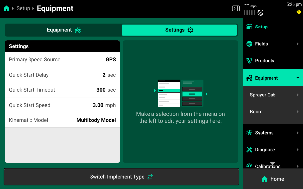
-
Swath - Once the machine has started spraying, use manual swath to go through nozzle by nozzle and make sure nozzles swath off in order. This will ensure that everything was set up in the correct location.
- If nozzles do not swath in the correct order, check harnessing setup for the CAN network those nozzles are on.
- If a nozzle is not spraying at all check Nozzle Solenoid setup to verify the port on the NCM it is plugged into is activated.
Manual Swath can be accessed through Product Control Widget> Swath Control
Diagnose
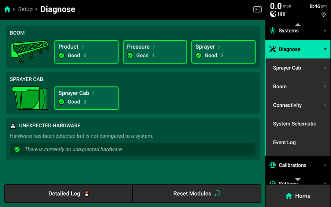
Sprayer Cab
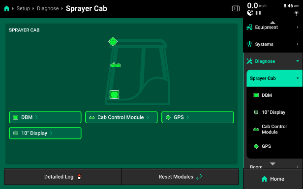
- DBM - Displays diagnostic information related to the Display Base Module.
- DBM Voltages - Displays constant and key switch power supply to the DBM.
- DBM Health - Displays battery and temperature status, and Missing Packets Correlation. A rapidly increasing MPC value indicates CAN communication issues.
- 20|20 CAN Bus A/B/C/D - Indicates network usage and percentage of errors in CAN packets sent/ received. If usage values exceed 80%, add another CAN network to the implement.
- Cab Control Module [CCM] - Displays the position of all switches on the CCM.
- Display - Displays Display Serial Number
- CCM Connected - Shows whether CCM is detected or not.
- GPS - GPS diagnostics are located under the Cab. GPS will be displayed in red until proper GPS communication is established with the receiver.
- Baud Rate - Measures communication speed between the GPS receiver and 20|20. A rate of 38400 is recommended for Precision Planting systems.
- Satellites in View / Average - An In View value lower than the Average value may result in reduced performance.
- Fix Quality - RTK is recommended for all Precision Planting control systems.
- HDOP - Horizontal Dilution Of Precision [HDOP] - Values exceeding 1 may result in lower performance.
- Reported / Calc. Speed - Difference between these values may cause control issues.
- Time - Displays current time/time zone. Inaccurate values indicate poor GPS communication.
- NMEA Messages received - Displays the rate (per second) that the GPS receiver is sending NMEA strings to the 20|20. All Precision Planting systems require 5 Hz.
- Speed - Displays all speed metrics and their status.
All Precision Planting systems require 5 Hz.
If GPS is configured on the Implement in Equipment setup, GPS diagnostics will be listed under the Planter on the diagnose screen.
Product
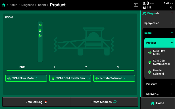
Within the Product system on the diagnose page you will have at least 2 categories to choose from, SCM Flow Meter and Nozzle Solenoid. On sprayer where OEM swath integration is being used, there will be a third system called SCM OEM Swath Sensor.
- SCM Flow Meter
- Flow Rate - Rate in Gallons Per Minute the flow meter is reading.
- Sensor Value - Showing pulses the system is reading from the flow meter in one second. Sensor A Value will appear on every sprayer; Sensor B Value will only appear on systems that utilize dual flow meters.
- Nozzle Solenoid - will display Current (A) and Duty Cycle for the nozzle bodies.
- Current (A) - Displays the current in amps being used to control the solenoid, this will be between .1-.3 when spraying.
- Duty Cycle - Displaying the % duty cycle we are commanding to each nozzle individually.
- SCM OEM Swath Sensor
- State - This wil say ON or OFF and this reflects the reading the system is getting form teh OEM Section Control System.
Pressure
Under the Pressure system there should only be one system. Hydraulic Pump Control OR Flow Regulating Valve.
- Hydraulic Pump Control
- Pump. Boom, and Sparge (psi) - Displays pressure at each of these locations based on the port the pressure sensor was plugged into on the PDM.
- Duty Cycle - Displays the duty cycle % the system is commanding to the pump at that moment. If the pump is not turning on and running this is a good location to check and make sure the pump is being commanded to spin.
- Pump Current (A) - Displays the current, in amps being used to control the solenoid on the pump.
- Flow Regulating Valve
- Pump, Actual, and Sparge (psi) - Displays the pressure at each of these locations based on the port the pressure sensor was plugged into on the PDM. Actual Pressure will be displaying the reading from the “boom” pressure sensor.
- Valve Direction - Displays the commanded position of the valve. “Forward”- The valve opening, “Reverse”- The valve is closing, “Stop”- The valve is not commanded to move.
- Pump Current (A) - Shows the current, in amps being used to control the Flow Regulating Valve.
Sprayer
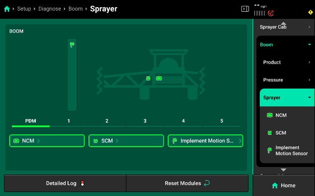
- NCM
- Supply (V) - Supply voltage to each NCM.
- Current (A) - Shows the amperage being used by each NCM during operation. This should be between .1- 1.
- Implement Bus CAN Errors - CAN communication errors between each NCM and the 20|20.
- Local Bus CAN Errors - CAN communication errors between each NCM and the hardware modules connected to it.
- SCM
- Supply (V) - Supply voltage to the SCM.
- Current (A) - Shows the amperage being used by the SCM during operation. This should be between .1- 1.
- Implement Bus CAN Errors - CAN communication errors between the SCM and the 20|20.
- Local Bus CAN Errors - CAN communication errors between each SCM and the hardware modules connected to it.
- Implement Motion Sensor -
- Supply (V) - Supply voltage to the IMS.
- Turn Rate - Displays the degree of turn currently deetected by the IMS.
- Acceleration - Displays the speed reading of the PDM-mounted IMS.
Error Codes
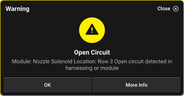
Nozzle Warnings
Open Circuit
A warning that will pop up on the 20|20 screen if the system does not detect a coil present when commanding a duty cycle to the nozzle body. This means that the coil may be unplugged or there may be damage to the 2-pin jumper harness.
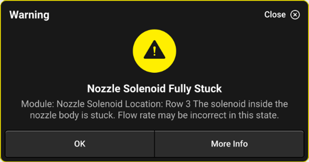
Nozzle Fully Stuck
A notification that appears when the system does not sense any movement from the poppet inside of the armature assembly. It may be stuck fully open or closed, make sure to stop and inspect the assembly for plugging.
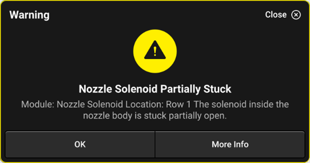
Nozzle Partially Stuck
A notification that appears when the system does not sense full range of motion from the poppet inside of the armature assembly. It may not be applying the correct rate if it can’t move freely inside, make sure to stop and inspect the assembly for plugging.
Pressure Warnings
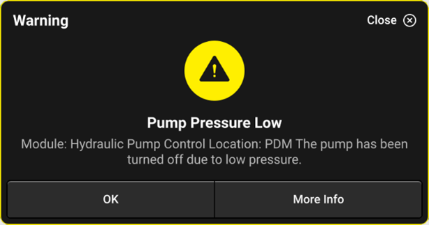
Pump Pressure Low
A safety warning that will appear when there is no pump pressure detected. This is put in place to keep the pump from damage if it runs dry.
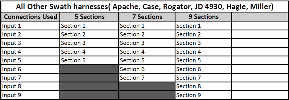
Appendix A - Swath Sensor Inputs
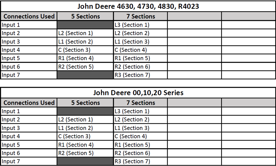
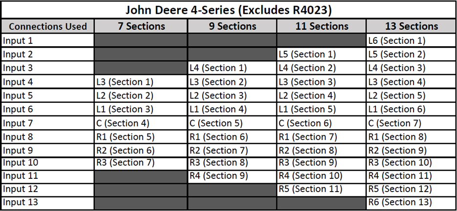
Sprayer tables for Swath Sensor inputs for SCM OEM Swath Sensor Section.
John Deere Sprayers (Minus 4-Series)
John Deere 4-Series and R-Series Sprayers (Exludes R4023)
General Sprayer Harnesses