SymphonyVision Operator's Guide
2025.10.x Limited Release Software is adding additional features throughout the 2025 season. This document will receive regular updates, and your version may be out of date. It is highly recommended to only operate SymphonyVision on the most recent version of 2025.10.x software, to download the most recent version, visit 2020.ag.
2025.10.x can only backdate to 2025.1.x or 2025.0.x software.
Contents
- SymphonyVision Requirements
- Major Changes
- Equipment Setup
- System Setup
- System Settings
- Home Screen
- Operation
- Calibration
- Diagnose
SymphonyVision Requirements
- Hardware requirements for SymphonyVision control and scouting maps
- Gen3 20|20
- Gen3 Cab Control Module [CCM]
- SymphonyNozzle
- PWM controlled pump
- Requirements for SymphonyVision scouting snapshots
- Panorama subscription
For best value of SymphonyVision scouting and snapshots, it is recommended that the grower have in-cab connectivity (via hotspot, etc) and linked to their Panorama account.
- flow-regulating valve
- hydraulic servo valve controlled pump.
Major Changes
No new major changes.
Equipment Setup
Sometimes there are multiple ways to navigate to a specific screen on the 20|20 monitor. In this manual, we will be using the Navigation Menu on the right side of the screen.
Overview
The Equipment menu is used to configure, save, and load different cab or implement profiles. Use this menu to enter all Cab / Implement specifications and measurements, to configure GPS and Radar location and settings, and to set up Ethernet / CAN.
Switching implement will erase any unsaved changes to the active cab / implement profiles. Ensure to save all chages before switching implement.
Boom Settings
- On the Home Screen press Setup
- On the Setup screen press the Equipment tab on the Navigation Menu on the right side of the screen.
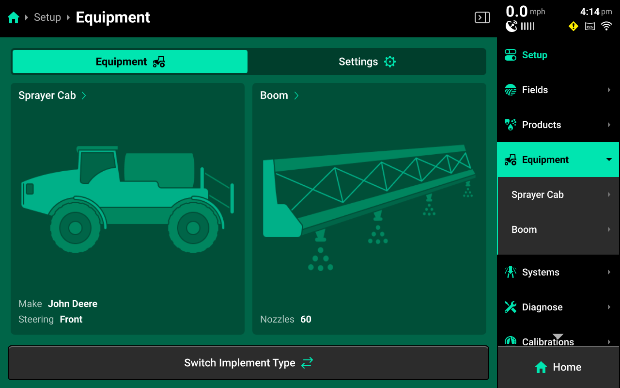
- Under Equipment a dropdown menu will appear with: Sprayer Cab and Boom
Press Boom
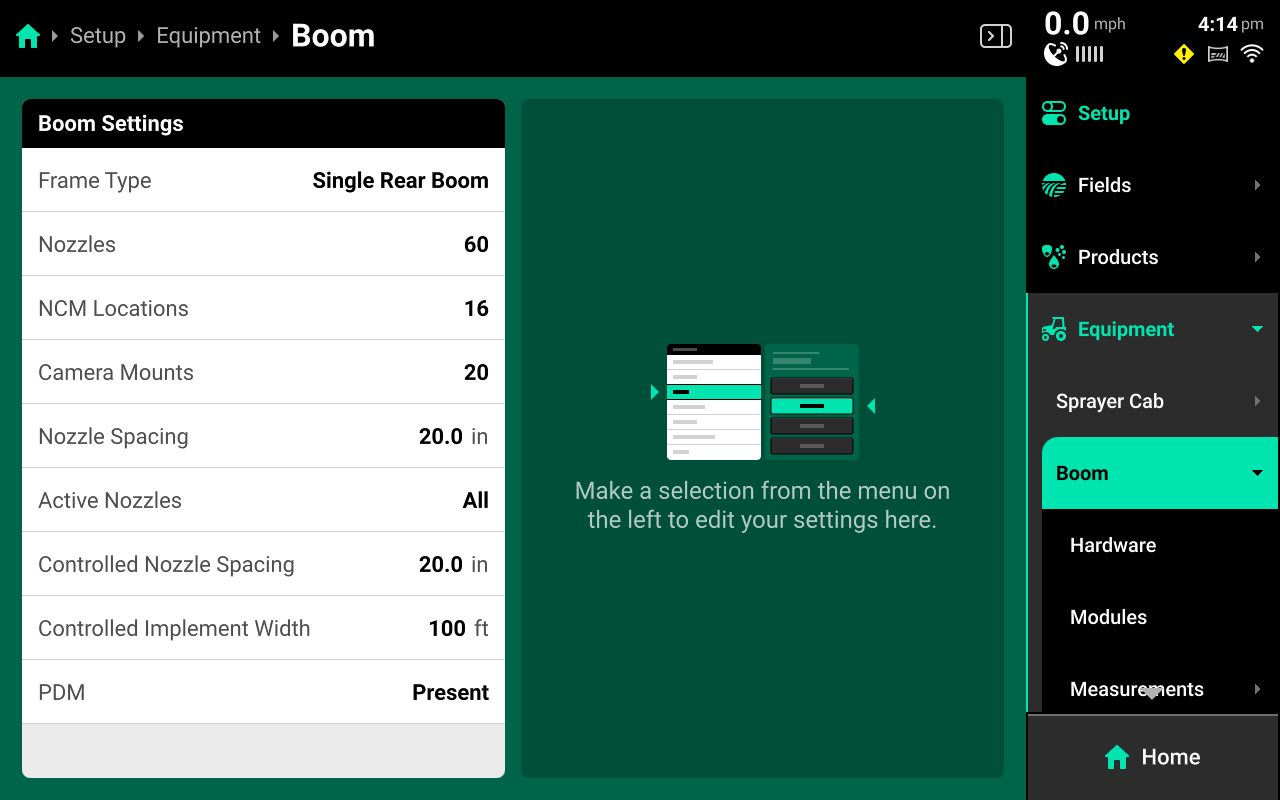
- On this Boom Settings screen, press the Camera Mounts selection button and input the amount of Vision Cameras that are installed on the sprayer.
Press Enter
Boom Modules
- In the Navigation Menu select Equipment, Boom, Modules to access the Boom Modules setup.
-
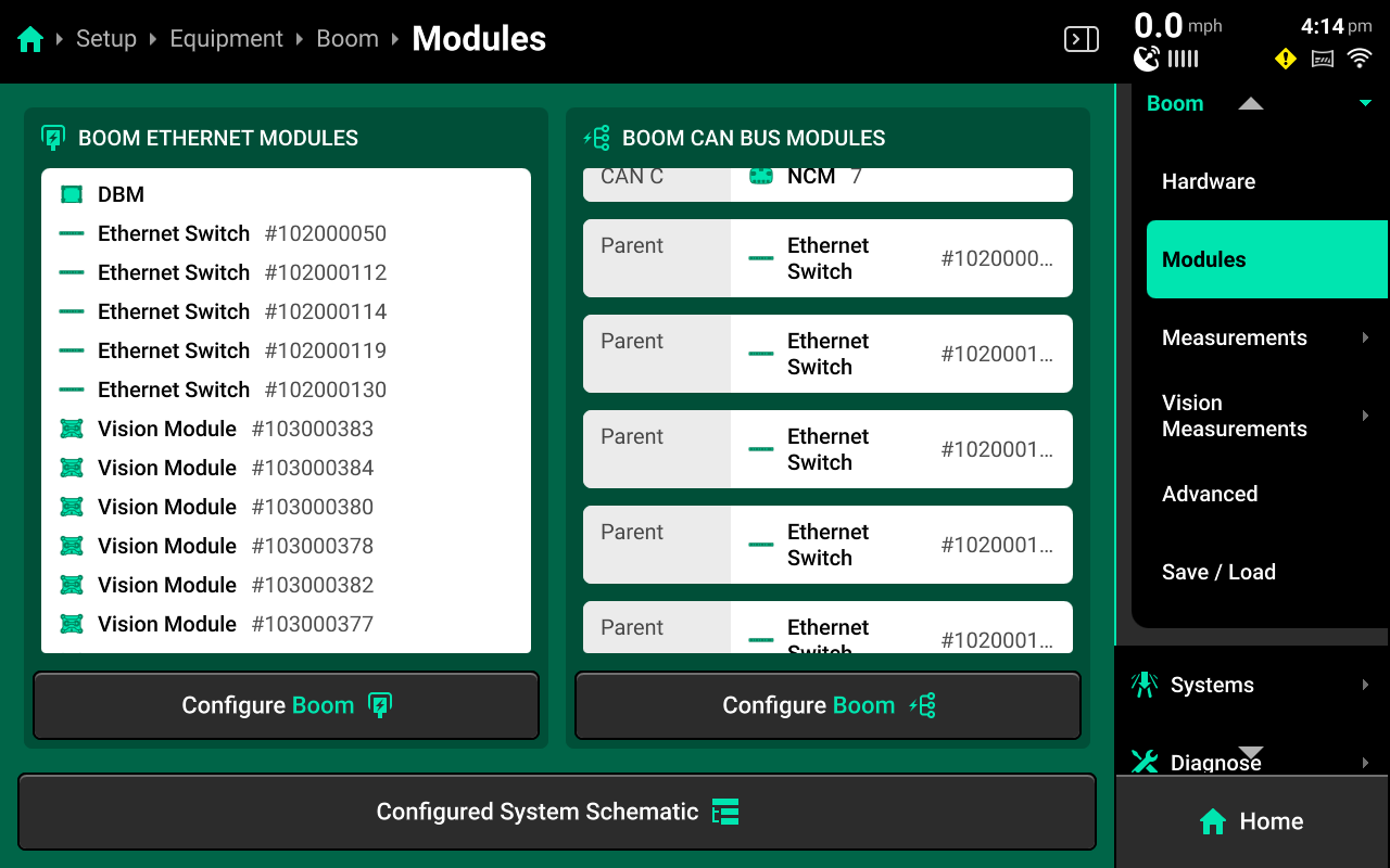
On the left side under Boom Ethernet Modules
Press Configure Boom
-
On the left side of the screen you should see configured modules, on the right are modules that have been detected, but are not configured yet.
-
Select the Ethernet Modules and Vision Modules installed on the boom.
Press Add Selected Modules
Press Continue
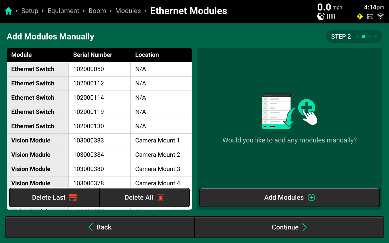
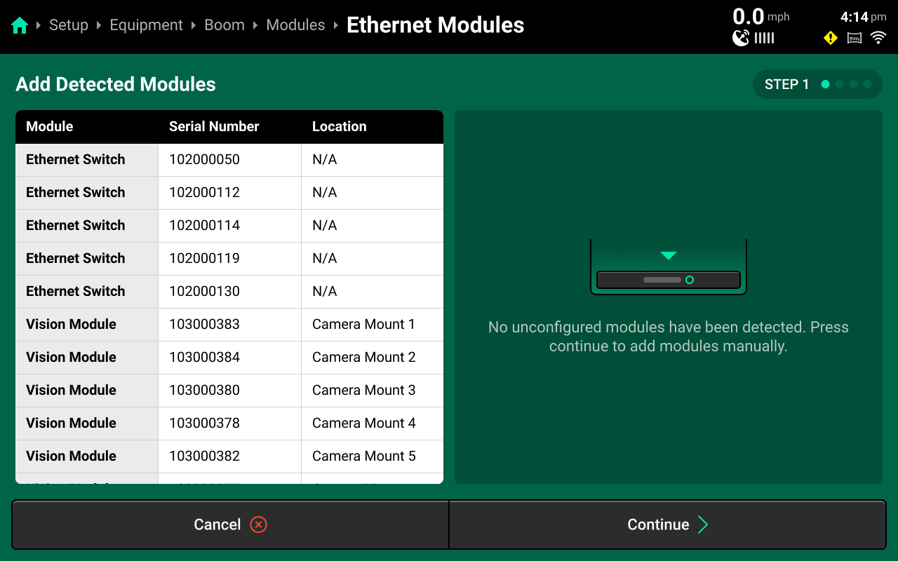
- If any modules were not automatically detected, this screen is to add them manually by pressing Add Modules and following the prompts.
Press Continue
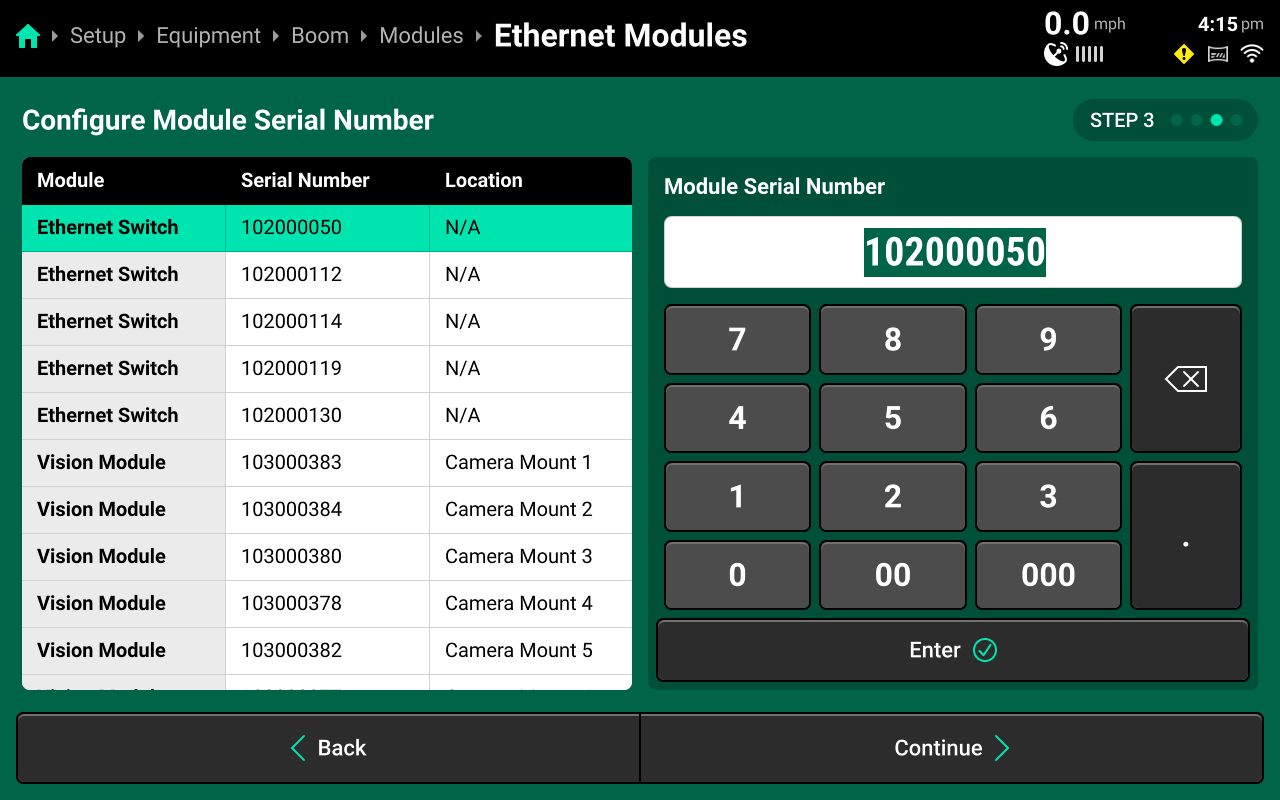
- Verify the Serial Numbers of the Ethernet Switches and the Vision Modules
Press Continue
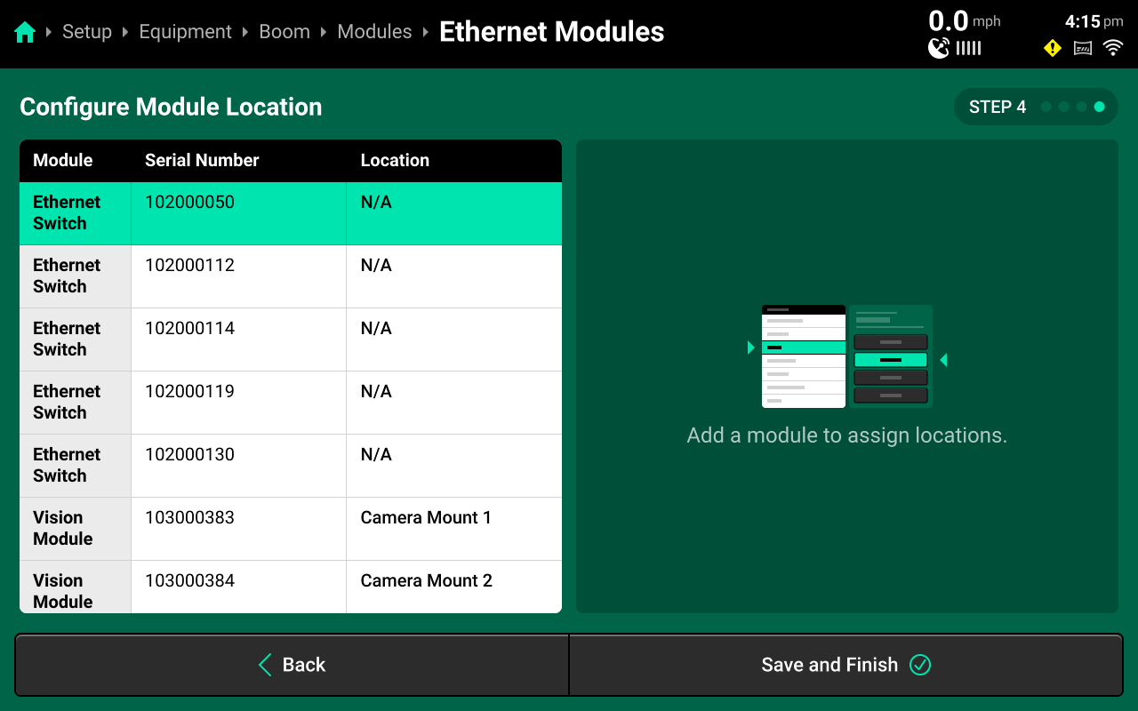
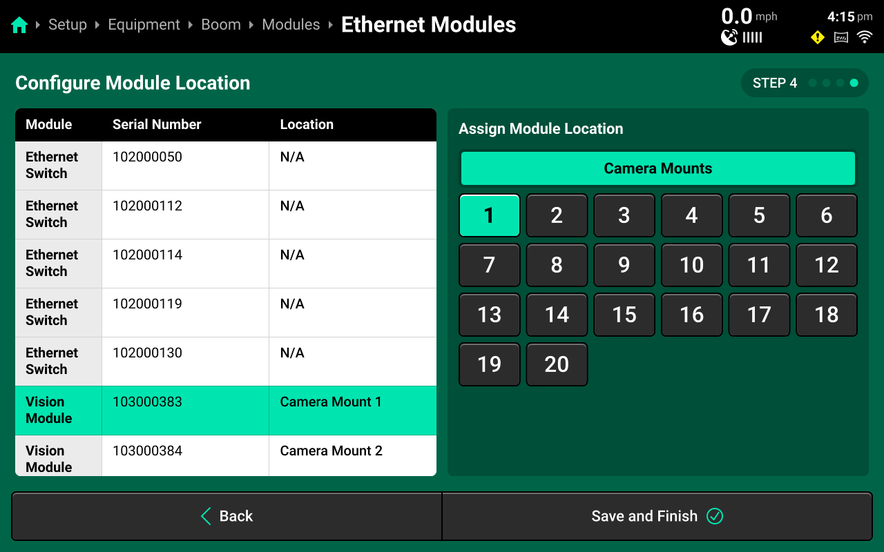
- On this screen, each Vision Module must be assigned a Location across the boom. It is recommended to start on the left boom wing and label the Vision Module at the boom tip to Camera Mount 1 and continue across the boom left to right.
Press Save and Finish
Ethernet Switches and Displays have no assignable location, their location will show as N/A
Vision Module Measurements
It is critical for accurate SymphonyVision performance that camera measurements are correct, down to the inch. It is highly recommended to doublecheck measurements before inputting in the 2020 through multiple measurement methods, if possible.
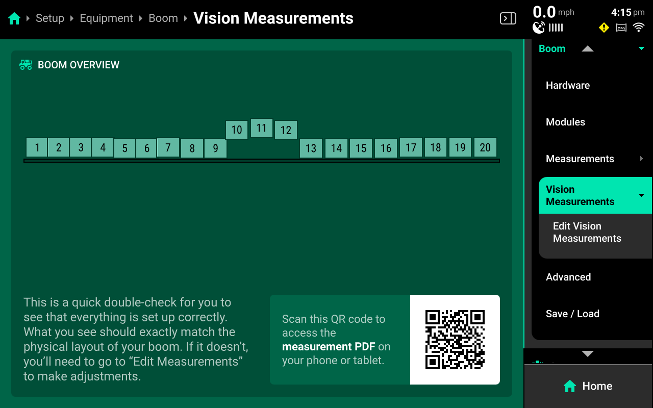
- In the Navigation Menu select Equipment, Boom, Vision Measurements, Edit Vision Measurements.
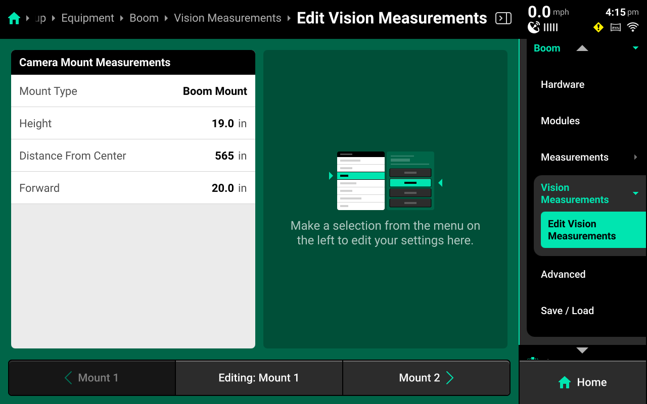
- For Mount location 1 and each consecutive mount, enter the following:
-
Mount type:
- Boom for boom mounted camera
- Chassis for any camera mounted above the wheels or center mounted on the sprayer chassis.
-
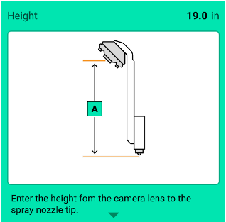
Height:
- For Boom mounted height: Enter distance in inches from center of camera lens to nozzle tip.
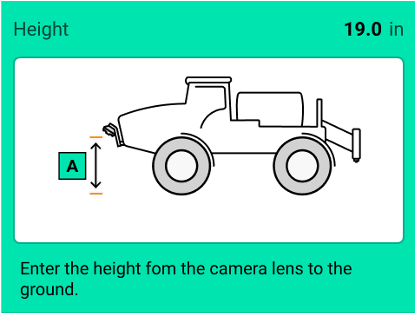
- For Chassis mounted height: Enter distance in inches from Center of camera lens to ground.
-
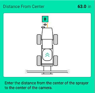
Distance from Center:
- For Boom Mounted: Choose Left of Center or Right of Center, enter distance in inches from center of sprayer boom to center of camera.
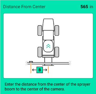
- For Chassis Mounted: Choose Left of Center or Right of Center, enter distance in inches from center of sprayer chassis to center of camera.
On 25.1.1, in order to choose Right of Center, it is necessary to first input a non-zero measurement and press Enter. Then you may choose Right of Center.-
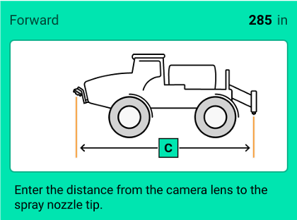
Forward:
- For Boom Mounted: Choose Behind Nozzles or In Front of Nozzles, enter distance in inches from center of camera lense to the spray nozzle tip.
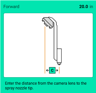
- For Chassis Mounted: enter distance in inches from center of camera lens to spray nozzle tip.
importantOn 25.1.1, in order to choose Right of Center, it is necessary to first input a non-zero measurement and press Enter. Then you may choose Right of Center.
Use navigation buttons at bottom of screen to navigate to previous or next camera mount and continue entering measurements untill all camera mounts are added.

-
Front mounted booms (Hagie, Miller, etc) will have Boom Mount for their Mount Type for all cameras.
- The Vision Measurements page visualizes the physical layout of the boom based on the measurements added. Double-check this page for a quick assessment of measurement accuracy.
System Setup
Overview
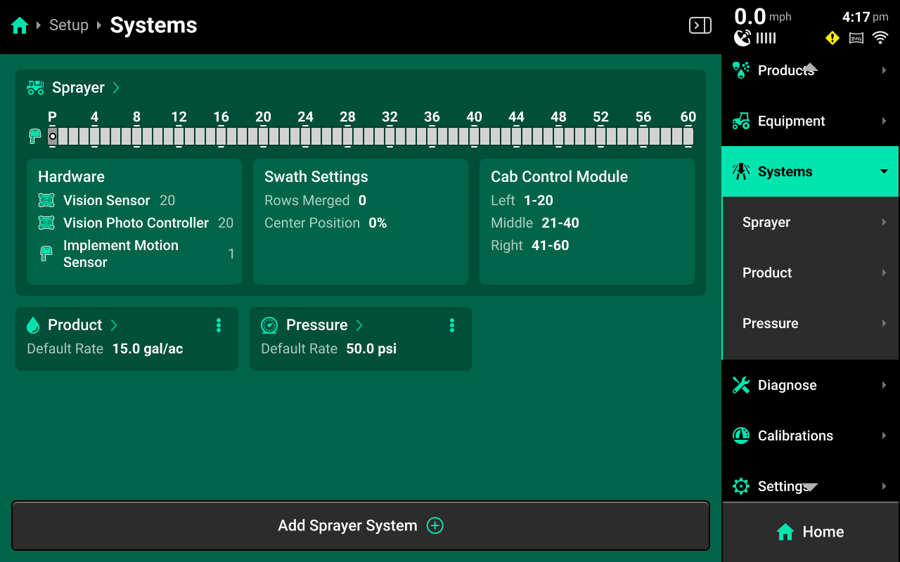
The Systems menu is used to configure all Precision Planting control and sensing hardware, System Alerts, swath settings and control sections. The user may also use the Systems menu to adjust Operation Settings for hardware, such as disabling failed sensors and enabling overrides.
The System Landing screen displays an overview of default system hardware, a summary of swath and CCM settings, and a list of all control and sensing systems which have been configured. The Vision Sensor and Vision Photo Controller will be visible here when it has been added and configured.
Vision Hardware Setup
- On the homescreen press Setup
- On the Setup screen, press the Systems tab in the Navigation Menu on the right side of the screen
- Under Systems a dropdown menu will appear with Sprayer. (Product, and Boom should also appear if SymphonyNozzle has already been configured)
Press Sprayer
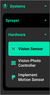
- Under Sprayer another dropdown menu will appear with Hardware
Press Hardware
- The Hardware* setup screen is where the Vision Sensor and the Vision Photo Controller can be added and setup.
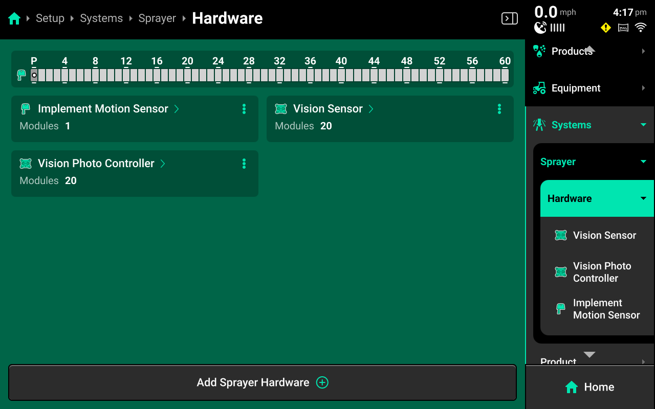
Press Add Sprayer Hardware at the bottom of the screen
- A window will pop up with Sprayer level modules. Vision Sensor adds the Vision sensor and allows sensor specific settings to be modified.
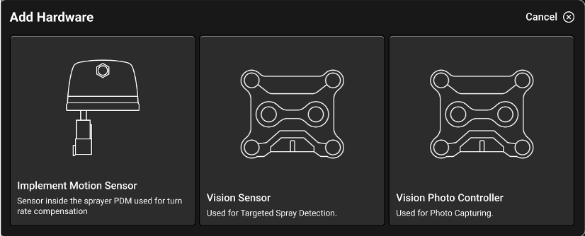
Press Vision Sensor
- Select all locations where SymphonyVision Modules have been added.
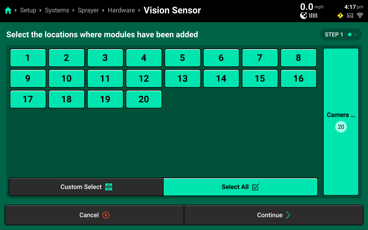
Press Continue
- Sensor settings may be modified on a per camera basis or Select All may be pressed to modify settings for all sensors at once. These settings will be explained further in Vision Sensor Settings

Press Save and Finish when settings have been modified to desired specifications.
- Back in the Hardware setup screen, the Vision Photo Controller will be added and setup next.
![]()
Press Add Sprayer Hardware
- A window will pop up with Sprayer level modules. Vision Photo Controller addes the Vision Photo Controller and allows snapshot specific settings to be modified.
Press Vision Photo Controller
- Select all locations where SymphonyVision Modules have been added.
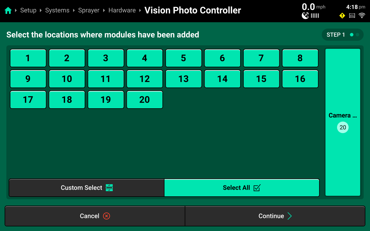
Press Continue
- Vision photo Controller settings may be modified on a per camera basis or Select All my be pressed to modify settings for all sensors at once. These settings will be explained further in Vision photo Controller Settings
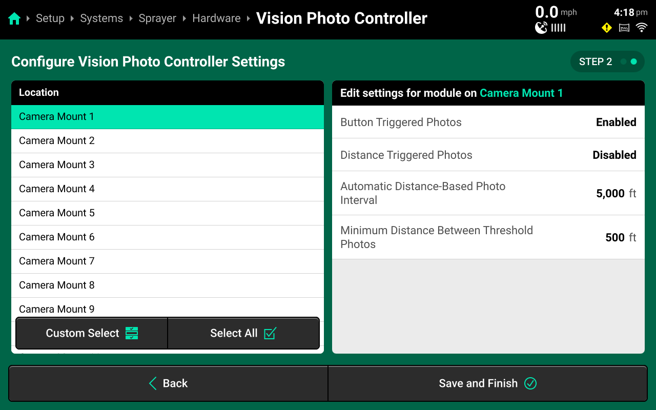
Press Save and Finish when settings have been modified to desired specifications.
System Settings
Overview
SymphonyVision has many customizable settings to modify how the SymphonyVision sensor detects, reacts, and snapshots weed and crop presence.
Vision Sensor Settings
The following Vision Sensor Settings can be modified:
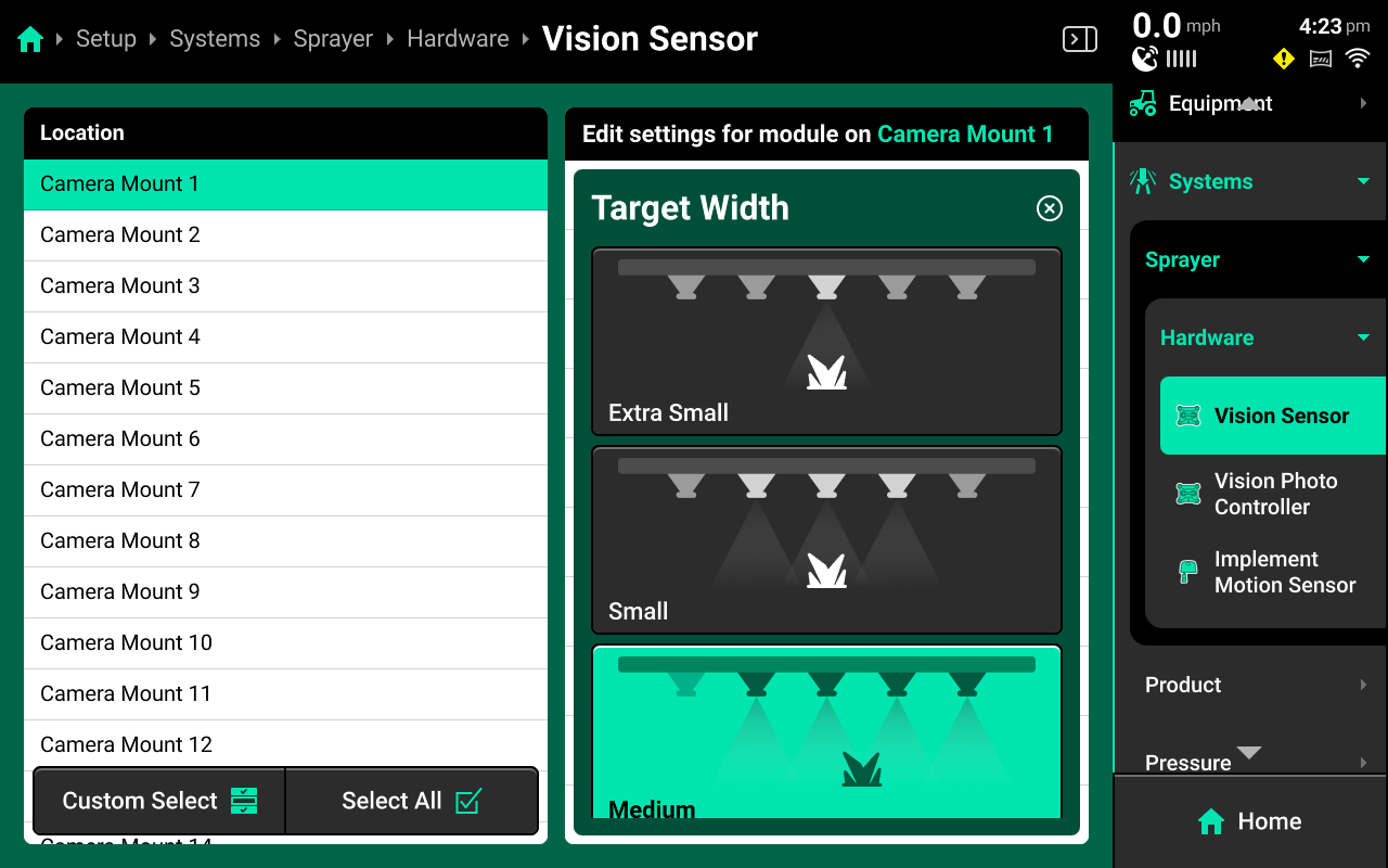
- Target Width - Minimum spray applied width based on distance from weed. (parallel to boom) Effectively, this setting adjusts how many nozzles will spray when a weed is detected.
- Extra Small - 1 nozzle minimum, 10" on either side of weed, only for testing or demo / not for use in-field
- Small - 2 Nozzles minimum, 20" on either side of weed, not recommended
- Medium - 3 Nozzles minimum, 30" on either side of weed, recommended setting
- Large - 5 Nozles minimum, 40" on either side of weed, very cautious setting
:::Note The minimum nozzles is an indication of the absolute minimum number of nozzles that will always spray on a particular setting when weeds are detected, in many situations, there will be +1 nozzle spraying due to actual location of weed in relation to nozzles. This is also based on 20" spacing as well.
:::
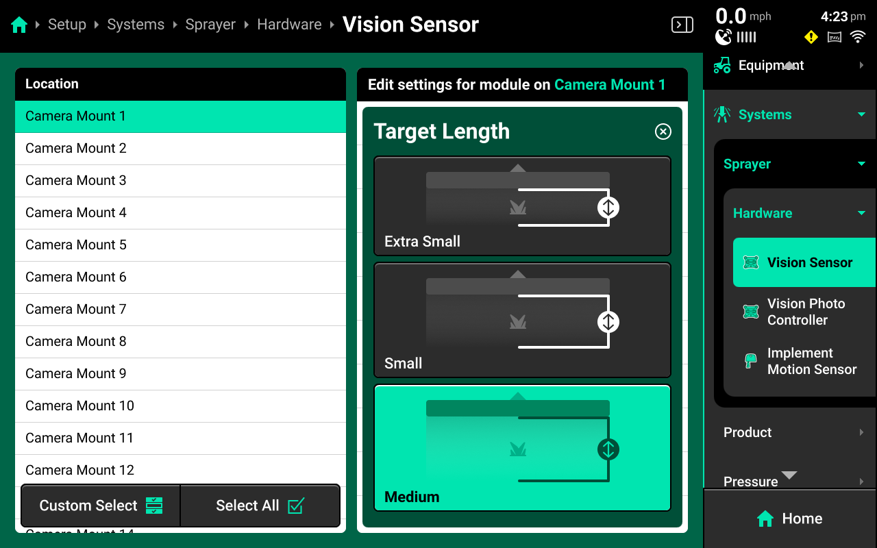
- Target Length - Minimum spray applied length based on distance from weed. (perpendicular to boom) Effectively, this setting adjusts the distance the nozzles will start and stop spraying before and after the weed when a weed is detected.
- Extra Small - 1 nozzle minimum, 12" before and after the weed, only for testing or demo / not for use in-field
- Small - 2 Nozzles minimum, 20" before and after the weed, not recommended
- Medium - 3 Nozzles minimum, 40" before and after the weed, recommended setting
- Large - 5 Nozzles minimum, 60" before and after the weed, very cautious setting
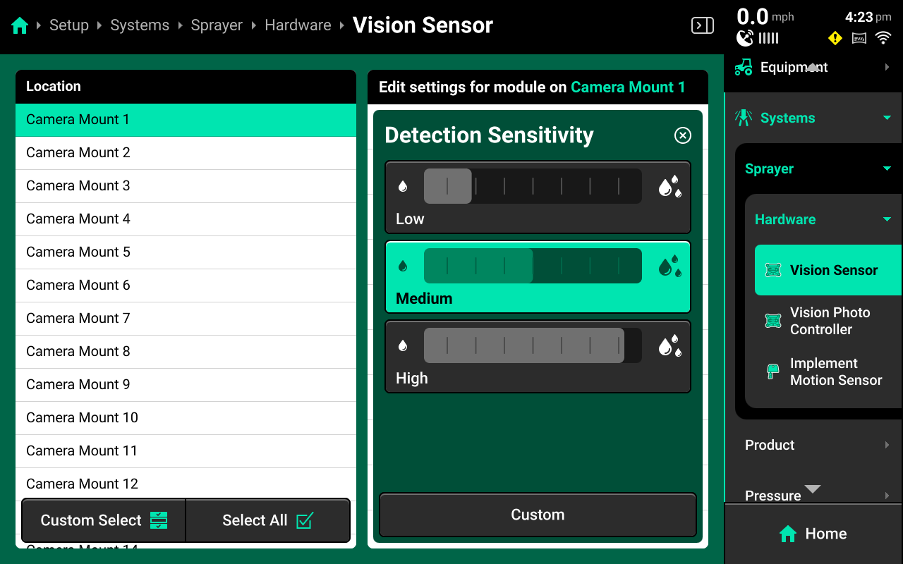
- Detection Sensitivity - Adjusts the weed detection threshold that determines when a spray application reaction will be commanded. The spray application reaction is determined by the severity and control settings.
- low - Less likely to adjust spray application / more savings
- Medium - Recommended
- High - More likely to adjust spray application / less savings
- Custom
- Crop Present - If spraying in a compatible crop, can be enabled for green on green spraying. Check compatibility list for current crop compatibility.
- Enable - Checks the active crop in the Field Settings and will enable green on green spraying in that crop if currently compatible. Any crop that is not currently active, will be sprayed as a weed.
- Disable - Disable for green on brown conditions, will detect all plants as a weed.
Weed Severity is the control metric used by the SymphonyVision system. This is a combined value of weed density (number of weeds) and weed size (height and width) of weeds in an area. The following settings allow the operator to dial in density and height settings for their specific conditions. These settings affect the control metric that informs application adjustments in the Weed Severity Control settings.
- Low Severity Max Density - This is the maximum density percentage that the sensor will consider a Low Severity.
For example, if the percentage is set at 25%, any weed density detected at 25% or less will be considered Low Severity for spray application adjustment.
- Medium Severity Max Density - This is the maximum density percentage that the sensor will consider a Medium Severity.
Continuing the above example, if this percentage value is set to 40%, any weed density detected between 25%-40% will be considered Medium Severity for spray application adjustment.
- Low Severity Max Height - This is the Maxmimum height in inches that the sensor will consider a Low Severity.
For example, if the height is set at 4", any weed height detected 4" or less will be considered Low Severity for spray application adjustment.
- Medium Severity Max Height - This is the Maximum height in inches that the sensor will consider a Medium Severity.
Continuing the above example, if this height is set to 8", any weed density detected betweeen 4" and 8" will be considered Medium Severity for spray application adjustment.
Weed Severity rating will adjust based on the metric with the highest rating at any given time. So from both of our examples, if the weed height is detected at 3", but the density is detected at 35%, our Weed Severity rating will be Medium.
- Weed Density Photos Enabled - Enable or disable the ability to snapshot based off of a Weed Density threshold.
- Weed Density Threshold - The threshold that must be met in order for a snapshot to be taken based on Weed Density
- Crop Health Triggered Photos - Enable or disable the ability to snapshot based off of a Crop Health threshold.
- Crop Health Threshold - The threshold that must be met in order for a snapshot to be taken based on Crop Health
Vision Photo Controller Settings
The following Vision Photo Controller settings can be modified:
- Button Triggered Photos - enable or disable snapshots that can be manually taken from a widget on the homescreen.
- Distance Triggered Photos - enable or disable snapshots based on distance thresholds.
- Automatic Distance-Based Photo Interval - Set the distance interval for Distance Triggered Photos (it is recommended to keep this distance to 5000')
- Minimum Distance Between Threshold Photos - When a Weed Density or Crop Health threshold snapshot is taken, this distance is the "rest time" before another threshold snapshot can be taken again.
For any triggered snapshots, it is recommended to only enable 1-3 cameras across the boom to keep snapshot data useful in Panorama. Be aware of the camera locations when assigning a trigger mode.
For best value of the scouting functionality, it is recommended to have in-cab internet connectivity (via hotspot, etc) and linked to their Panorama account.
Home Screen
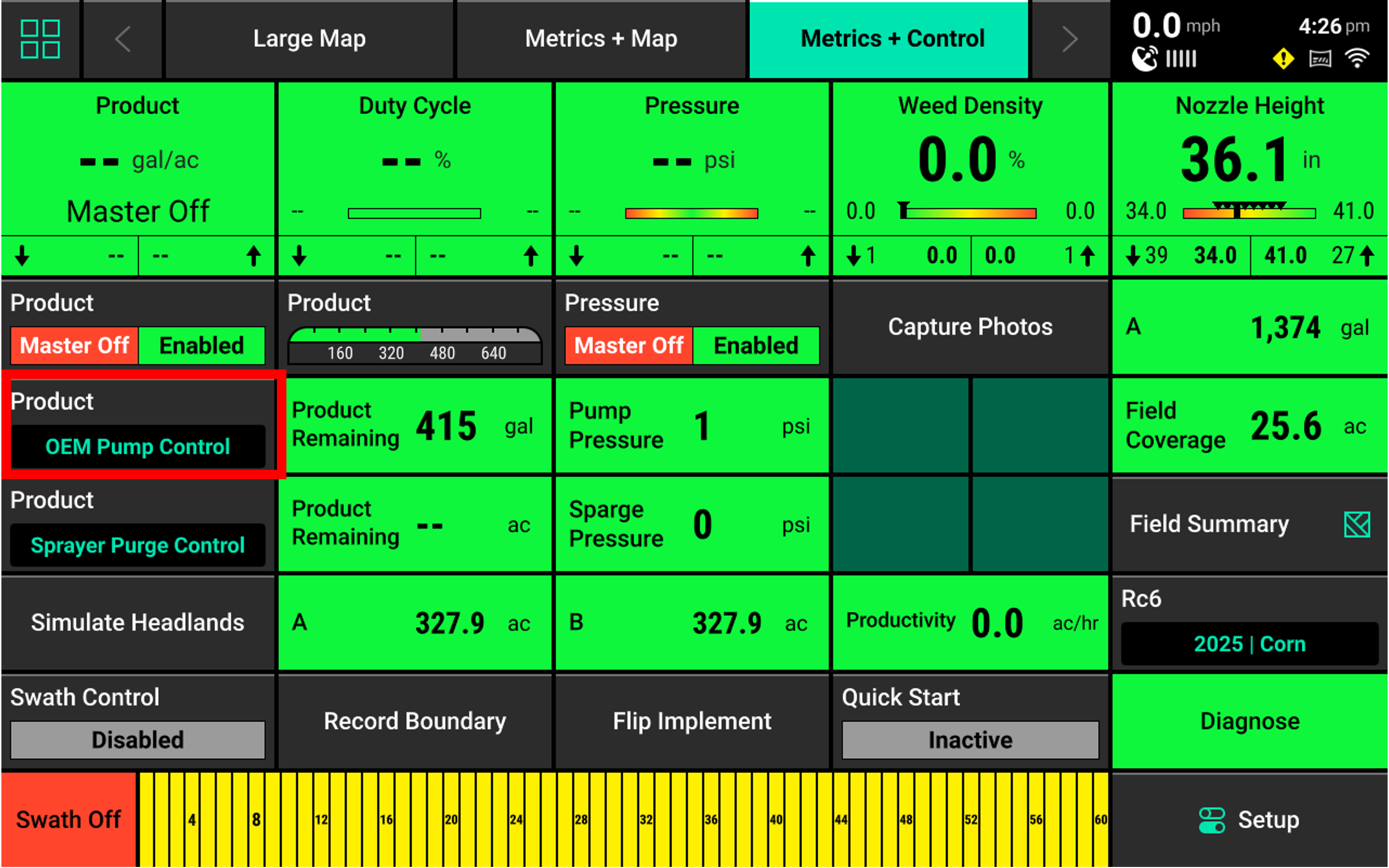
For SymphonyVision, the Home Screen displays scouting data for weeds and crops in an easy to read and navigate format. This information is presented as both metrics and high-definition maps. Additional screen configurations may be added and customized with different metrics, widgets, map sizes, controls, and minicharts. Screen configurations mya be toggled between by pressing the arrows at the top of the screen.
-image of homescreen w/ vision widgets-
The 20|20 displays high definition real-time maps while operating. Different map layers may be selected and viewed during operation.
Map Layers
Different maps are available for the SymphonyVision System. To view the map layer options, press the current layer name displayed in the top left corner of the map. A list of all available maps will be displayed.
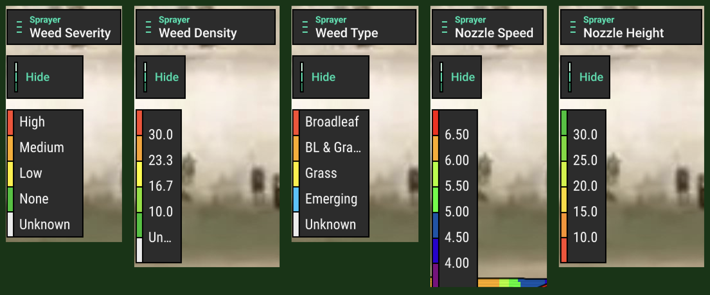
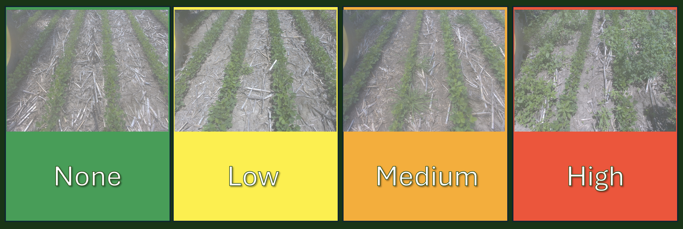
- Weed Severity - The control metric, displays a combined value of weed density and size (height and width) of weeds in an area.
- None - no weeds are detected
- Low - Determined by the Severity settings in the Vision Controller System
- Medium - Determined by the Severity settings in the Vision Controller System
- High - Determined by the Severity settings in the Vision Controller System
- Unknown - indicates no determination could be made
- Weed Density - Percentage value based on the number of weeds
- Weed Type - Displays weed identification as either
- Broadleaf
- Grass
- Broadleaf and Grass
- Emerging - This is a plant that is too small to be accurately identified as a crop or weed.
- None
- Unknown - indicates no determination could be made
- Nozzle Height - Height of nozzles in inches
Metric Widgets
Different widgets are available for the SymphonyVision System. To view the widget options, press the 4 squares in the top left of the Home Screen. In the bottom right, press Add Widget button. For detailed information on adding widgets please see the 20|20 Operator's guide.
- Weed Density - Percentage value based on the number of weeds
- Nozzle Height - Height of nozzles in inches
Control Widgets
Control Widgets may be added to the Home Screen in order to give control of some aspect of the product.
- Capture Photos - Allows the operator to capture a photo on any cameras that have manual snapshot enabled.
For green on green conditions, it is also recommended to have the ==Active Field== control widget on the homescreen for a quick verification of crop type set for the field.
Operation
Control Settings
- On the Homescreen, access the Product Control Screen
Press Product Control Widget
- Activate Sensor Control, Product Control must be enabled
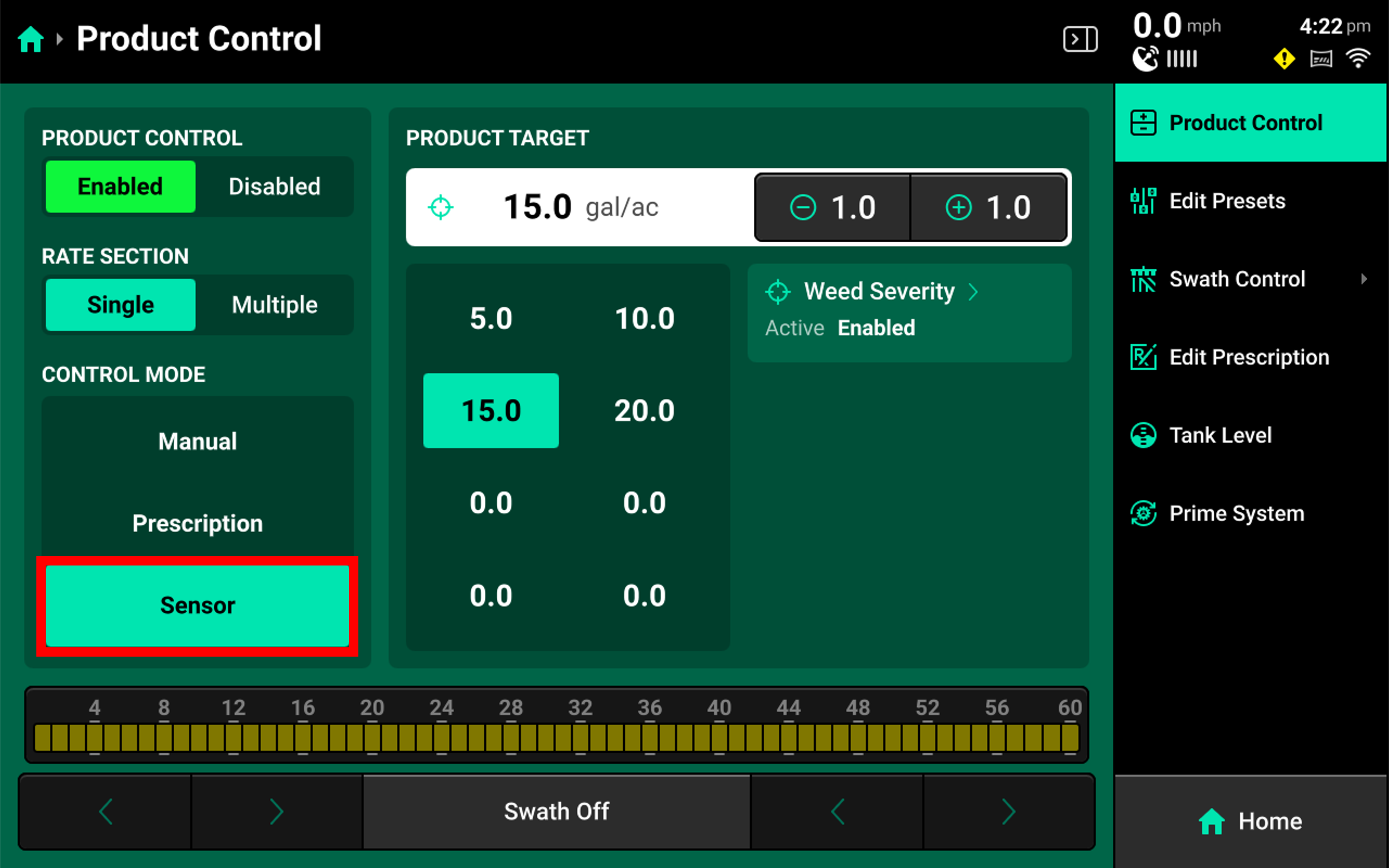
Choose Sensor for the Control Mode
- In order to set target adjustment %, first Set a Product Target Rate
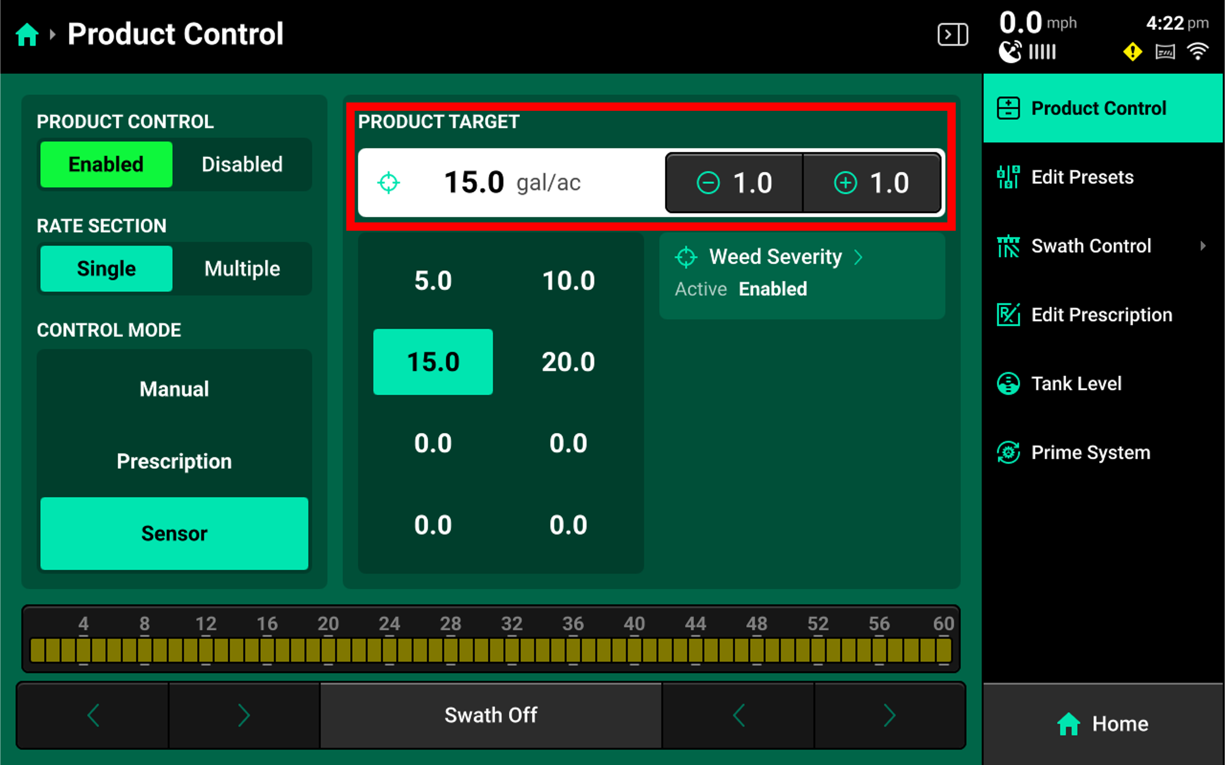
Press Weed Severity to access control settings
- Access the Weed Severity Control Settings
Press Settings tab at top right of screen
- Here you can enable control and set your control height parameters.
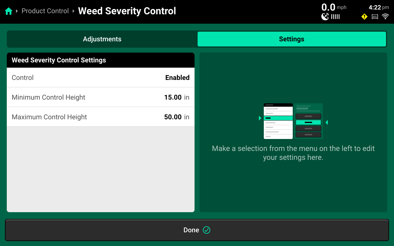
- Control - Enable or disable Weed Severity Control rate adjustment
- Minimum Control Height - When SymphonyVision detects the spray tip is below this height, spray application will default to 100%.
- Maximum Control Height - When SymphonyVision detects the spray tip is above this height, spray application will default to 100%.
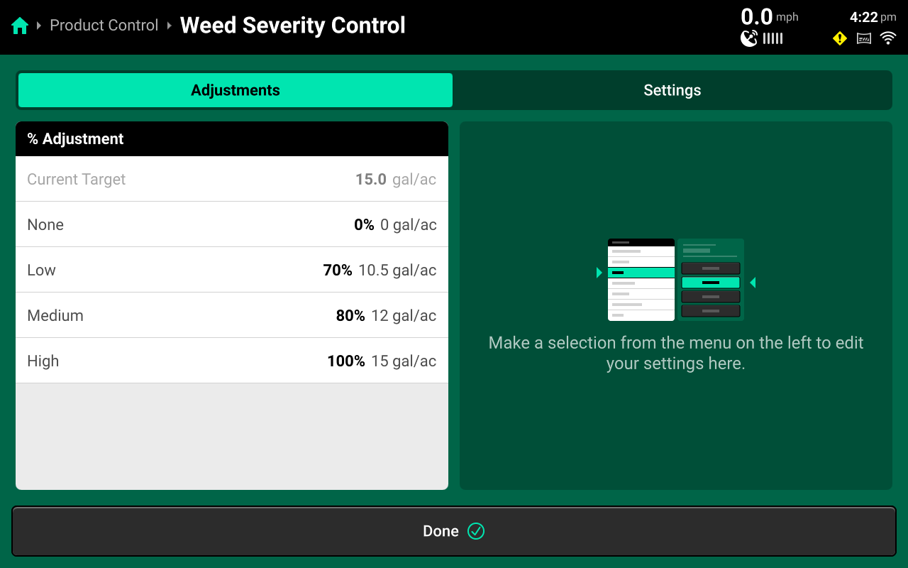
Weed Severity Control Screen
Homescreen > Product Control Widget > Product Control: Enabled > Control Mode: Sensor > Weed Severity Button
- Access the Weed Severity Control Adjustments
Press Adjustments tab at top left of screen.
- Spray application variable rates can be set on this screen.
Rate Adjustments Settings
Before setting your rate adjustments, consult with your chemical representative and Chemical labels to ensure all adjustments are within the boundaries set by the chemical label.
The Following Situations will cause SymphonyVision to default to 100% Rate:
- Unknown Weed Severity
- Too fast
-
15mph - Spot System
-
20mph - Rate System
-
- Out of min/max height range
- Poor Image conditions
- Physical Obstruction
- Dirty Lens, etc
- Extreme vibration or movement
- Too dark
Calibration
SymphonyVision Calibration
The SymphonyVision Calibration has the following requirements:
- Boom unfolded and at spray height
- 50-100ft of open space to run
- relatively flat and open ground
- On the homescreen, press Setup
- On the setup screen, press Calibrations
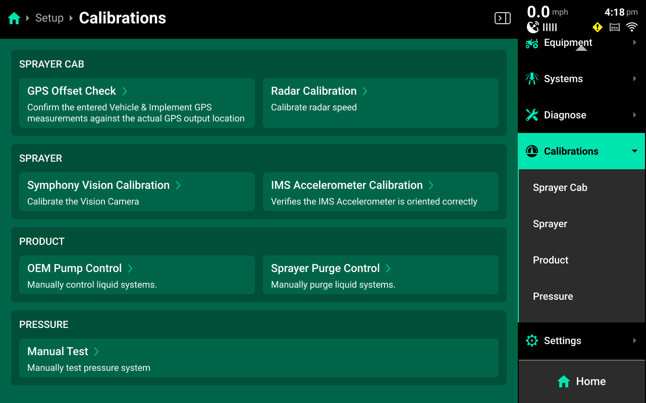
- On the Calibrations screen, under SPRAYER, press SymphonyVision Calibrations
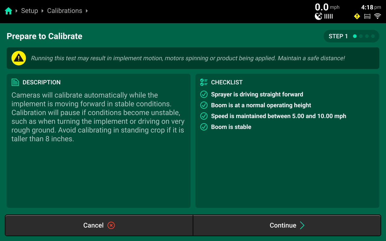
- Follow the instructions on-screen to start the calibration procedure
Press Continue
-
Select modules to run
Press Continue
-
Start Calibration
- Drive straight forward
- Boom at normal operating height
- Maintain 4-10mph speed
- Boom must be stable
If you reach the end of useable running space, the calibration will automatically pause while you turn around. When you have completed your turn and are on a stable and straight course, the calibration will continue.
- When Calibration progress reaches 100% on all selected rows, you may stop the sprayer.
Press Continue
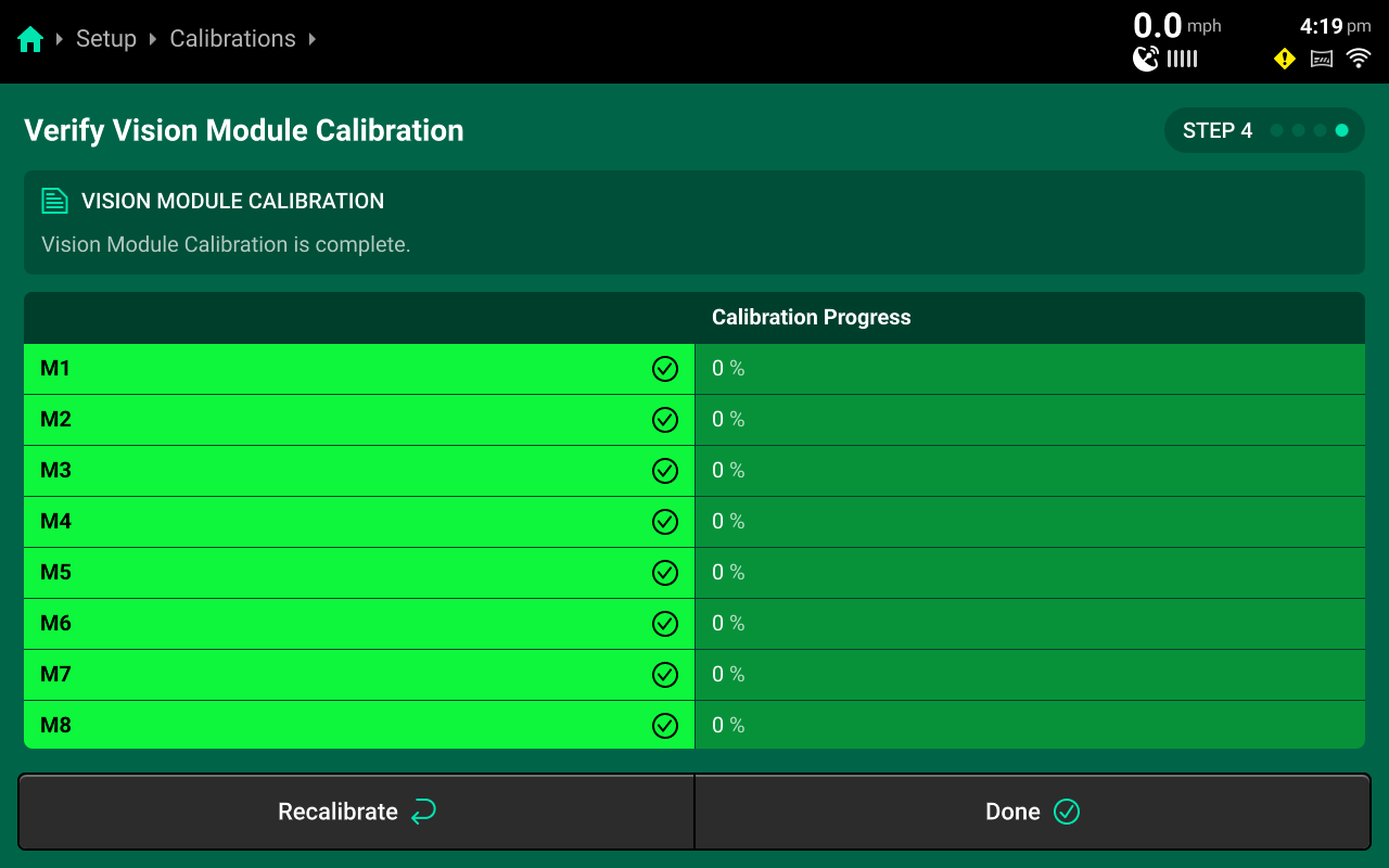
- On step 4, you may verify that all rows have completed the calibration and are at 100%. If necessary, you may Recalibrate from this screen as well.
Press Done
- Calibration is complete.
Diagnose
Overview
The Diagnose Menu is used to identify and troubleshoot hardware device failures and configuration issues in the 20|20.
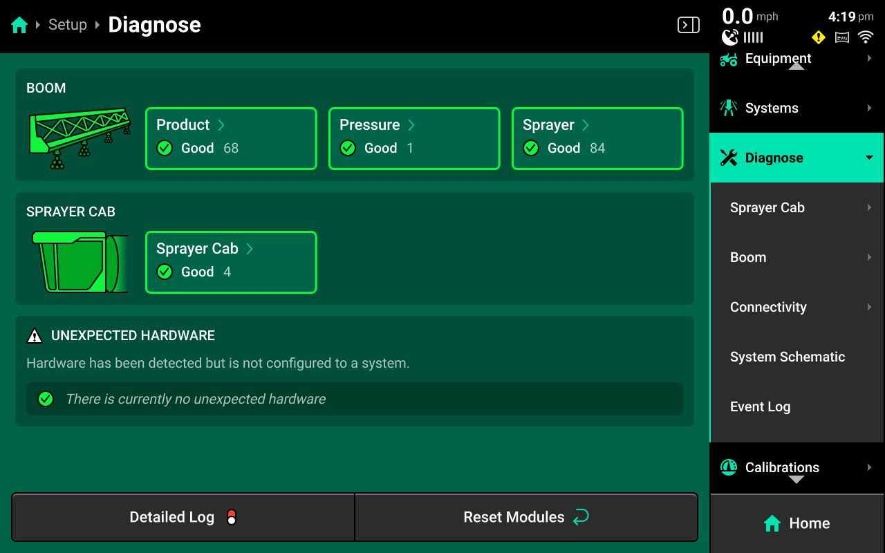
Use the following colors to determine device status on the Diagnose screen.
Green : Device is working correctly. Communications are good. Yellow : Device or sub-component is not 100% functional. Red : Device has failed, or is expected and not detected. White : Device is detected but not expected. Black : Device has been disabled by the user. Grey : Device is finishing detecting or unreachable. Teal : Device is updating firmware.
Diagnose Page
The Diagnose Landing Screen displays an overview of overall implement and cab system health.
Diagnostics
| Event Popup | Solution |
|---|---|
| Bad Calibration | Re-calibrate |
| Connection between sensors and main controller has failed | Reset modules, Restart DBM |
| Too great a distance between cameras | Check measurements in setup / Measure and adjust camera distance |
| Lens obstruction | Clean lenses |
| Sprayer moving too fast | Slow down |
| Boom unstable | Slow down, check what's causing boom instability - possibly field conditions, OEM height sensor calibration, boom hydraulics, etc |
| Bad configuration / setup | Check equipment Boom Settings for SymphonyVision - Camera mounts, modules, and measurements / Systems Settings - SymphonyVision Sensor and Photo Controller settings |
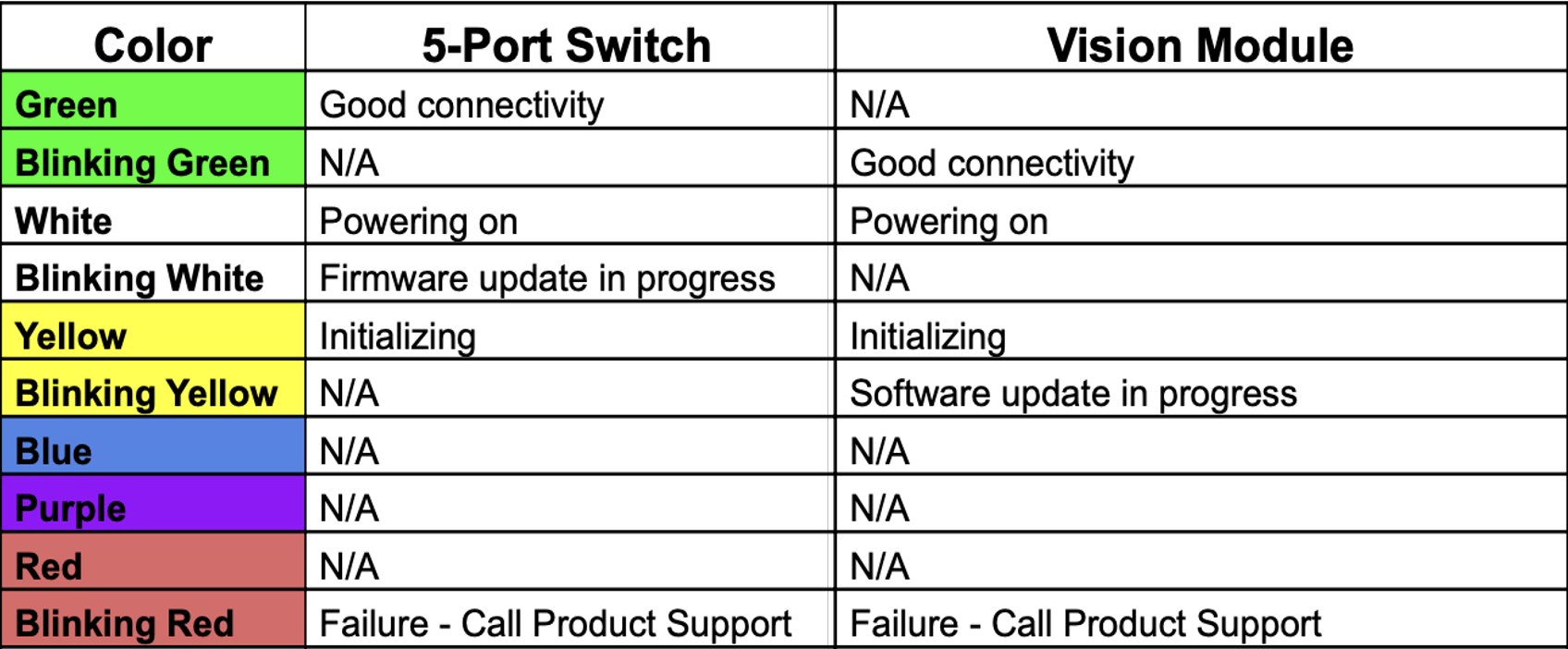
Indicator Light Overview
Use the following table to determine the status indicated by the LED on the corresponding device.
Appendix A
Data Sharing
On initial update to 25.10.x software, a Data Sharing selection will be available on the screen. Data Sharing helps to improve SymphonyVision weed detection, crop detection, and any other future sensor based detection.