DeltaForce Operator’s Guide
Contents
- DeltaForce Requirements
- Home and Control Screens
- System Setup
- Hardware Setup
- System Settings
- Alerts
- Calibrations
- Diagnostics
This guide is intended for use with limited release software 2025.1.0 and its variants. Due to the nature of the limited release software update process, screenshots and descriptions provided in this guide may differ from the current version. Updates are made to this guide as often as possible. To download the most recent version of Gen 3 software, visit 2020.ag
DeltaForce Requirements
DeltaForce Operation Requirements
- DeltaForce system configured on the 20|20.
- Down Force Sensor / Row Solenoid / Lift Manifold / Hydraulic Pressure Sensor installed and configured.
- Default Down Force Target set.
- Speed source active.
- CCM master plant switch in the up position.
- Implement must read lowered.
- Down Force system enabled.
Safety Warning
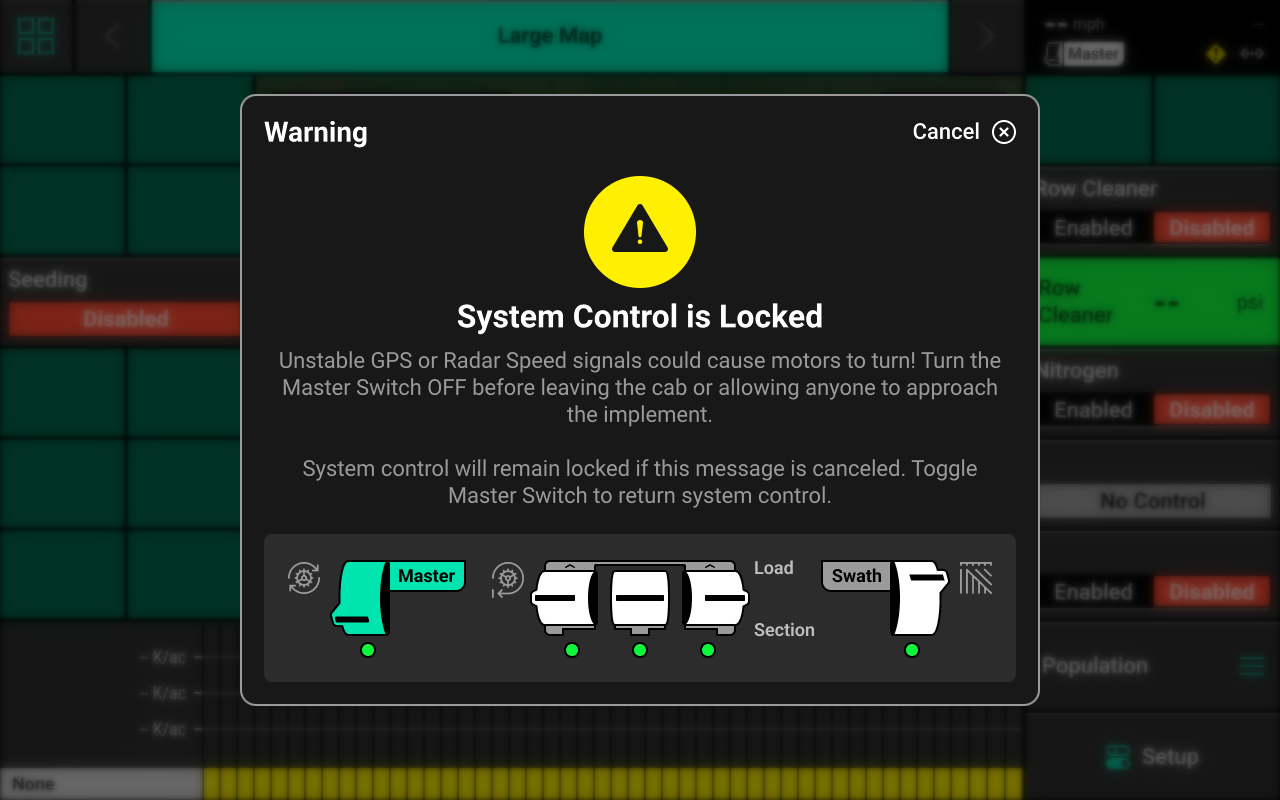
If any control product is configured on the 20|20 display, the system will require a CCM and will prompt the user to toggle the Master Plant switch on the CCM before any control products may be used. This warning is triggered any time the system is booted up, and when the system has traveled for more than half a mile. Pressing cancel will bypass this warning. No control systems will operate until the Master Plant switch is toggled. The Master Icon will be present in the top right of the 20|20 screen in the Status Center if the safety warning was bypassed.
Home and Control Screens
Home Screen
The home screen displays information for controlling and mapping the DeltaForce system.
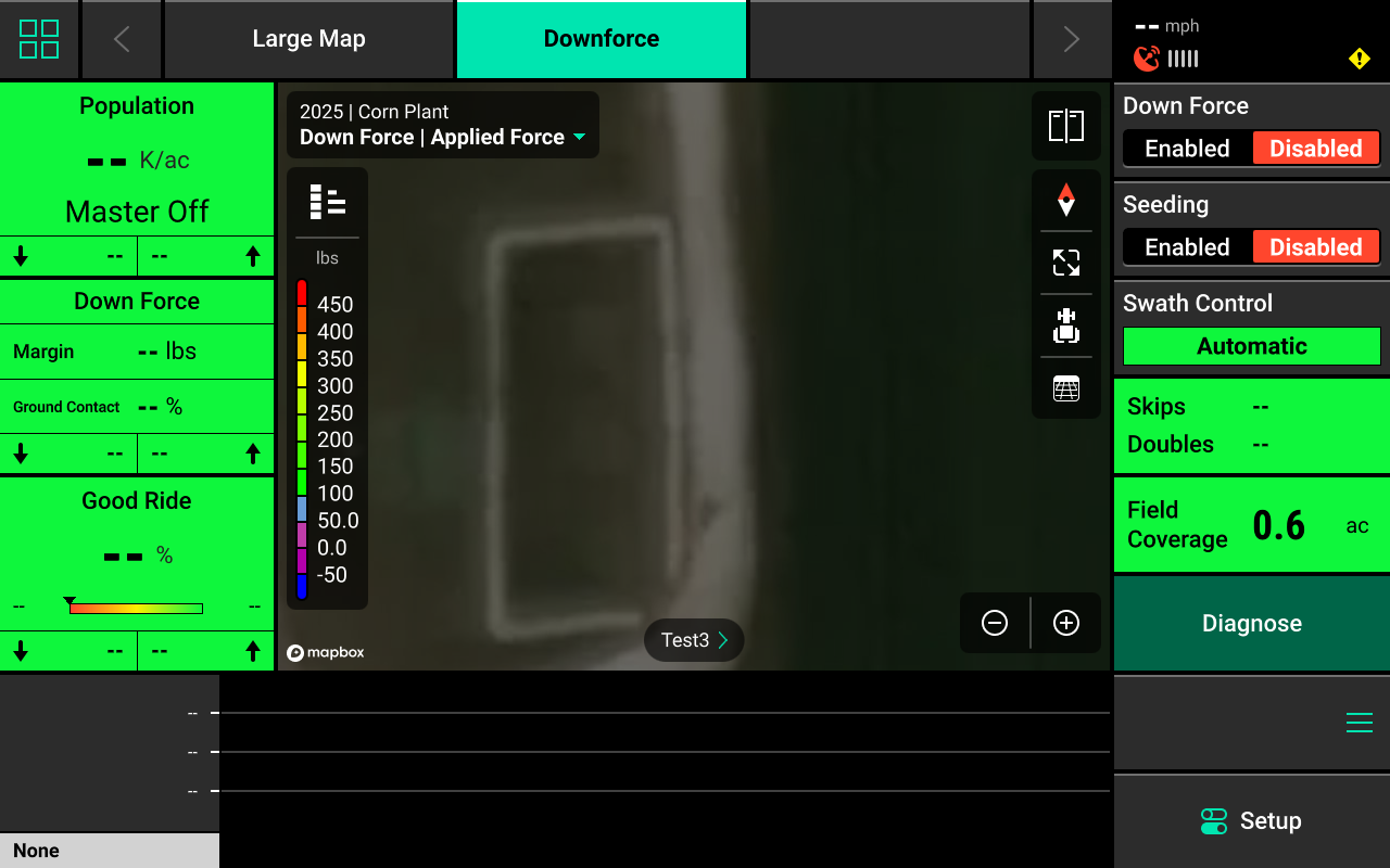
Metric Widget
The Metric Widget displays current load sensor weight values to help indicate if we are experiencing any down force preformance issues.
- Margin: Displays the planter wide average of the lowest measured load sensor readings in pounds.
- Ground Contact: Displays the percentage of time the system can confirm that the gauge wheels have met the depth stop. This is calculated by the percentage of time that the load sensor is measuring above 20 Ibs
- Low and High Row: SHows the average load sensor readings for the lowest and highest rows.
DeltaForce Mapping
Different maps are available for the Down Force system. To view the map layer options, press the current layer name that is displayed in the top left corner of the map. A list of all available maps will be displayed.
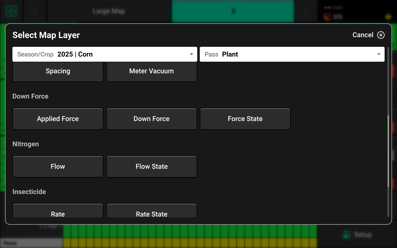
- Applied Force — Displays cylinder commanded force on a row-by-row basis.
- Down Force— Displays load cell readings on a row-by-row basis.
- Force State - Displays alert/ alarms readings.
If a Down Force prescription or field boundary is assigned to the active field, the prescription / boundary file will be available as a map layer.
See the 2025.1.x Gen 3 Operator's Guide for definitions of these and other metrics.
Control Widget
A Control widget for the DeltaForce system must be placed on the home screen before the system will function. Press the Four Squares in the top left, then press Add Widget + in the bottom right and select Controls to view options. Some Control widgets include a toggle which allows the user to enable or disable the system without opening the Control screen. Other control widgets include quick adjust buttons for population change. Press the different sizes on the right to view all options.

Control Indicators
- Enabled : The system is ready to plant.
- Disabled : The system will not plant. To enable the system, toggle the system to enabled using the control widget.
- Lifted : The system will not plant due to lift switch reading.
- Master Off : The master plant switch on the CCM is off or the safety warning was bypassed. The system will not plant.
- Sensor : The system is using a sensor (e.g. SmartFirmer) for population control.
Control Screen
Once the Control widget has been added to the Home Screen, press it to open the Control screen.

Control Mode
Select the desired Control Mode to control Down Force manually, or by prescription.
Manual Control
Allows the user to manually select a Down Force Target for one or more rate sections. This setting ignores any assigned prescriptions.
Rate Sections
- Single : One Down Force Target across all rows.
- Multiple : Up to 4 different Down Force Target's across preconfigured sections of the planter. See System Settings in this guide for more details.
Select the desired section mode and set the desired Down Force Target(s) using the presets in the center. Press the number displayed under Seeding Target in the center to manually enter a Down Force Target (Single rate section only). Press Edit Presets on the right to modify the table of preset population values.
Manual Swath Control
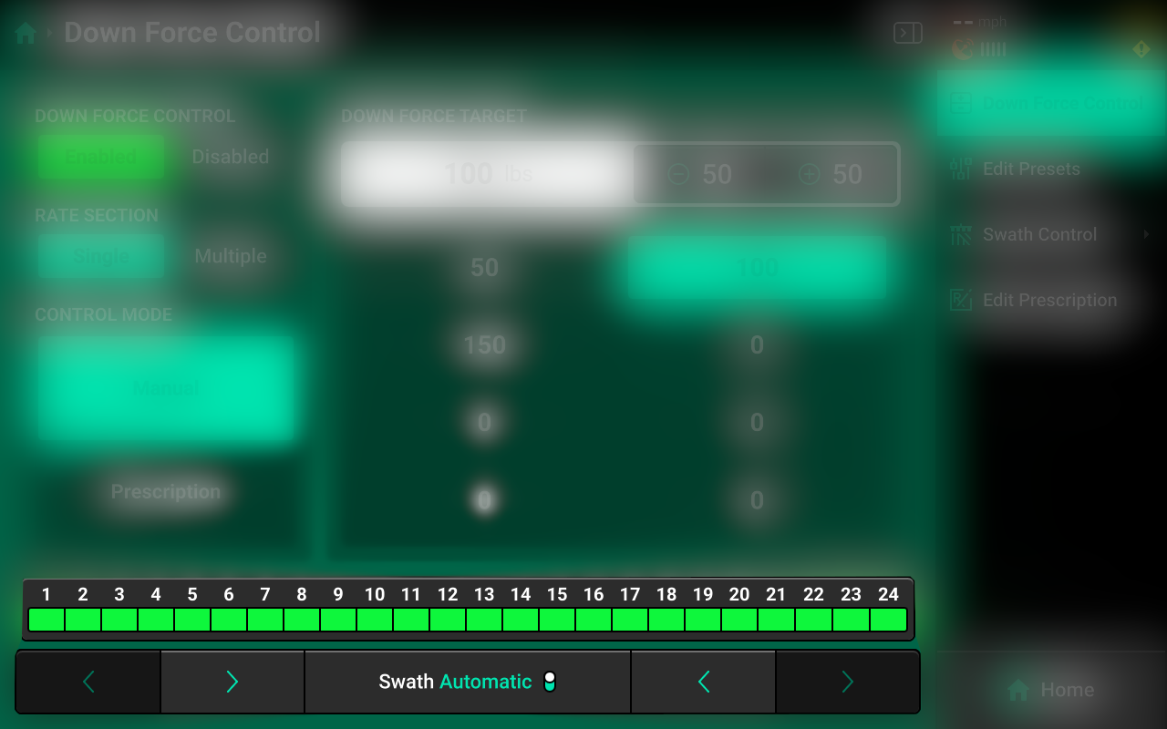
A Swath Control Bar is displayed at the bottom of the control screen. Press any row in the bar to swath that row off and engage Manual Swath Mode. Rows may also be clutched off from left-to-right or right-to-left using the arrows below the Swath Control Bar.
In Manual Swath Mode, the 20|20 will no longer swath off to boundaries or coverage. To return to Automatic Swath Mode, press Swath Manual in the bottom center.
Swath Control Screen
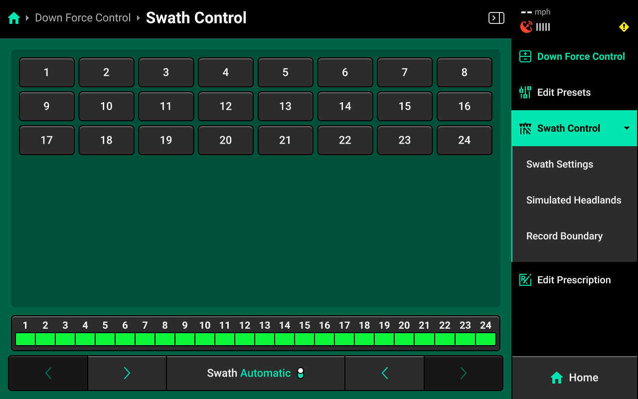
The Swath Control Screen allows the user to manually swath rows on / off, configure a swath control plan, record a boundary, or simulate headlands. For more information on these features refer to the Swath Control Section of the Gen 3 Operator's Guide.
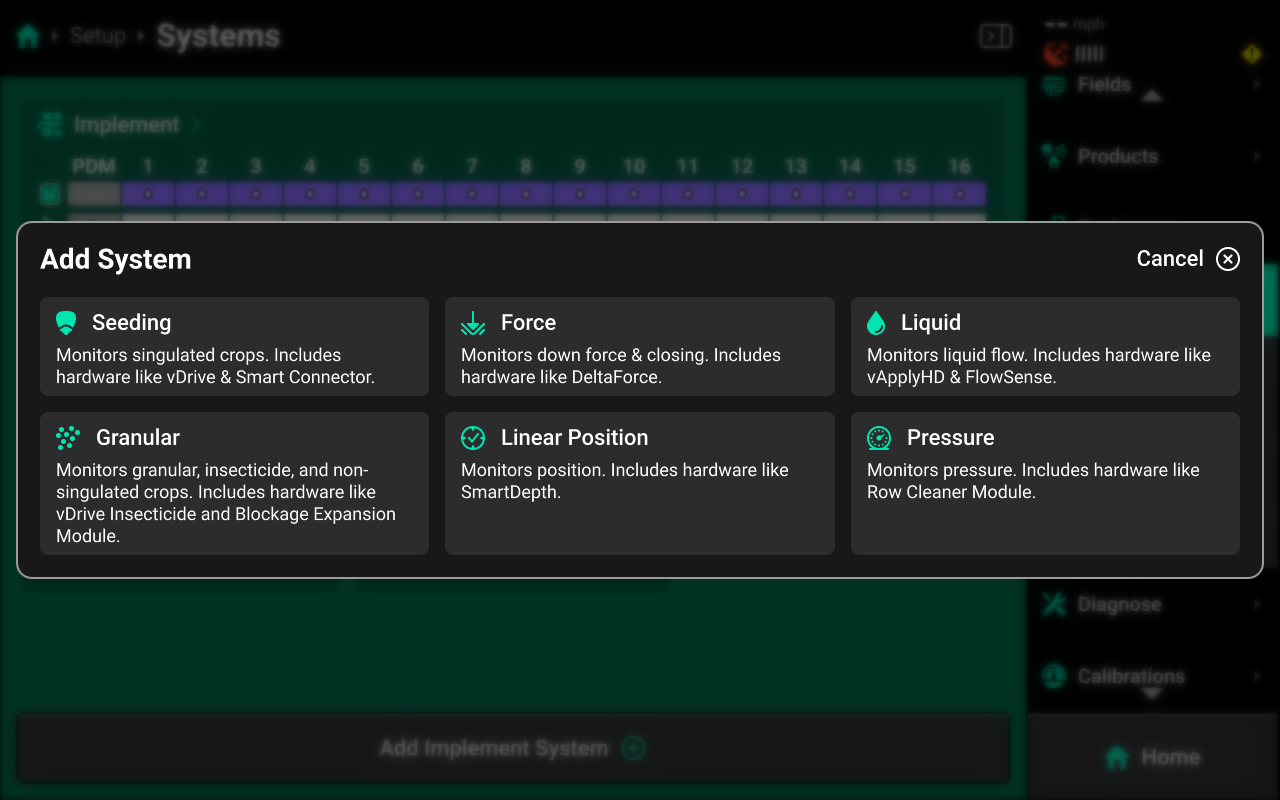
System Setup
DeltaForce requires a Force-type System to be configured in the 20|20. To configure a Force system, Navigate to Setup > Systems and press Add Implement System in the bottom center.

This guide assumes that all Equipment, implement-wide hardware and Ethernet / CAN modules have already been configured and calibrated. See the 2025.1.x Gen 3 Operator's Guide for more details on setting up / calibrating Equipment, Modules and other hardware.
Select Force from the popup, then select Down Force or enter a custom name from the second popup.
Hardware Setup
To configure DeltaForce hardware, select [Down Force System Name] in the Navigation Menu, then press Hardware under that system and use the following process.
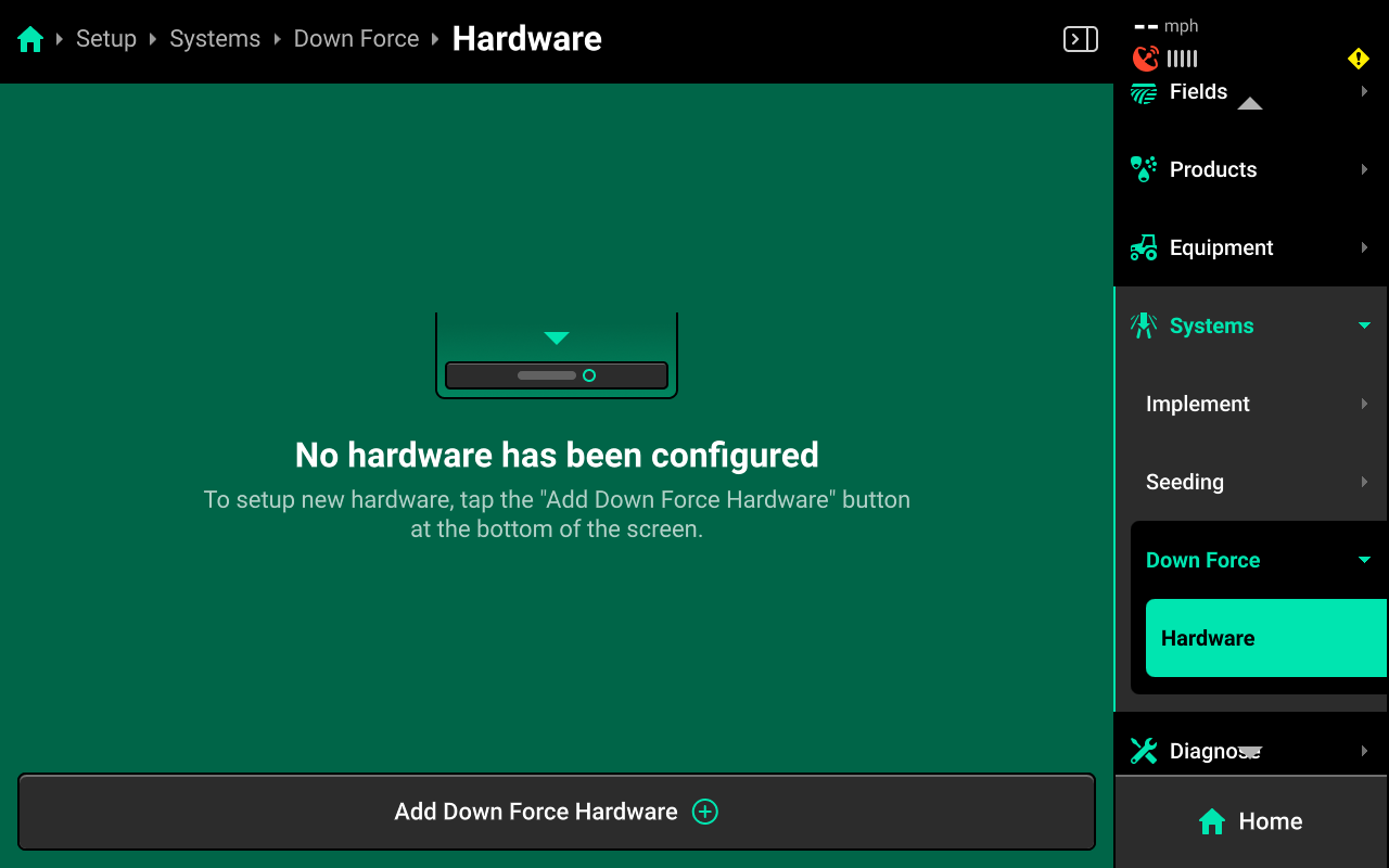
Down Force Sensor
Press Add [System Name] Hardware + and select Down Force Sensor from the popup to open the Down Force Sensor hardware setup wizard.

On Step 1, press each row in the table that has a Down Force Sensor installed, or press Select All in the lower right, then press Continue.

On Step 2 use the left window to Custom Select or Select All Rows, then use the right window to change the desired setting. Press Save and Finish to exit setup.
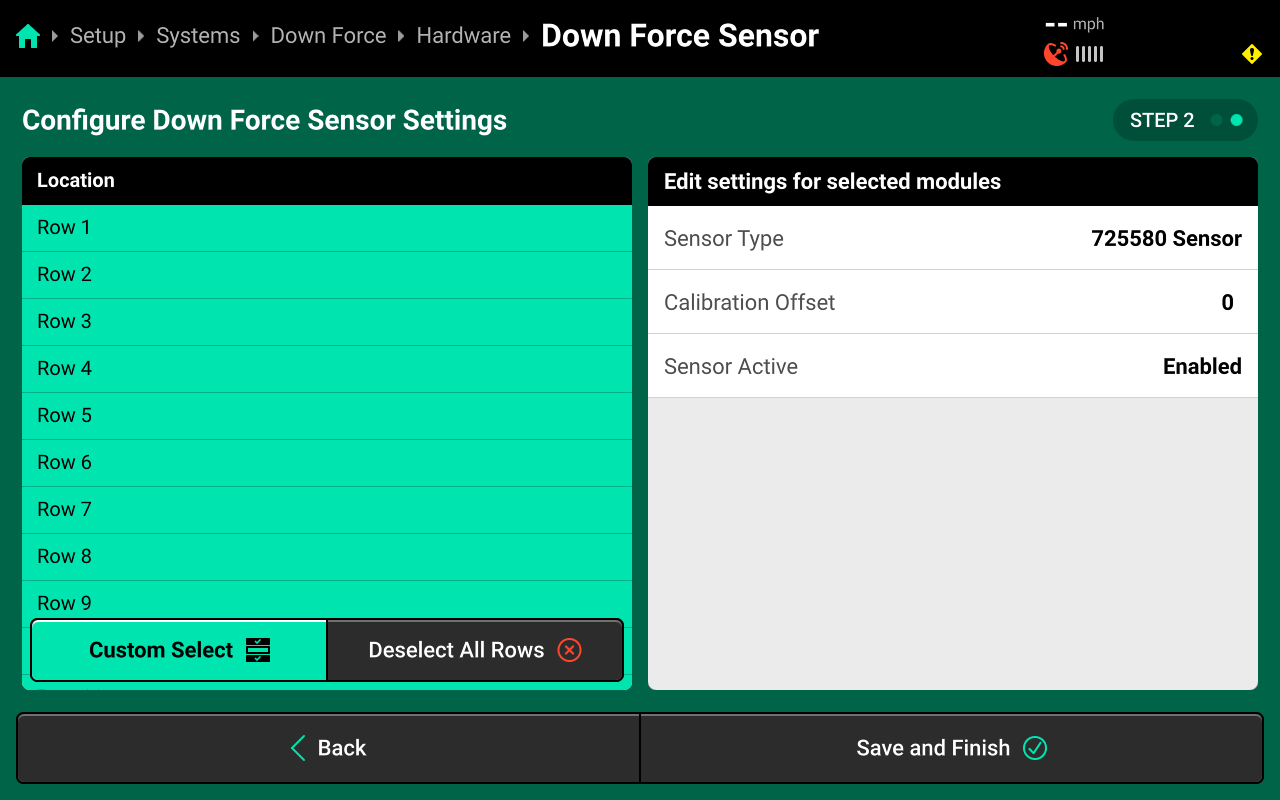
Sensor Type
- Select all rows and then select the sensor that is installed on the row unit.
Available Sensor Type will be determined by the Row Unit selected in the Planter Profile located at Setup > Equipment > Planter. All row units have the 725580 Sensor selected by default, Sensor Type will need to be changed for any row unit not using this sensor to ensure correct DeltaForce Function.
Calibration Offset
- This is the Load Sensor zero value, this offset will default to 0 until, the Zero Load Sensors Calibration is complete.
Sensor Active
- This function will allow you to enable/ disable Load Sensors.
DeltaForce Row Solenoid
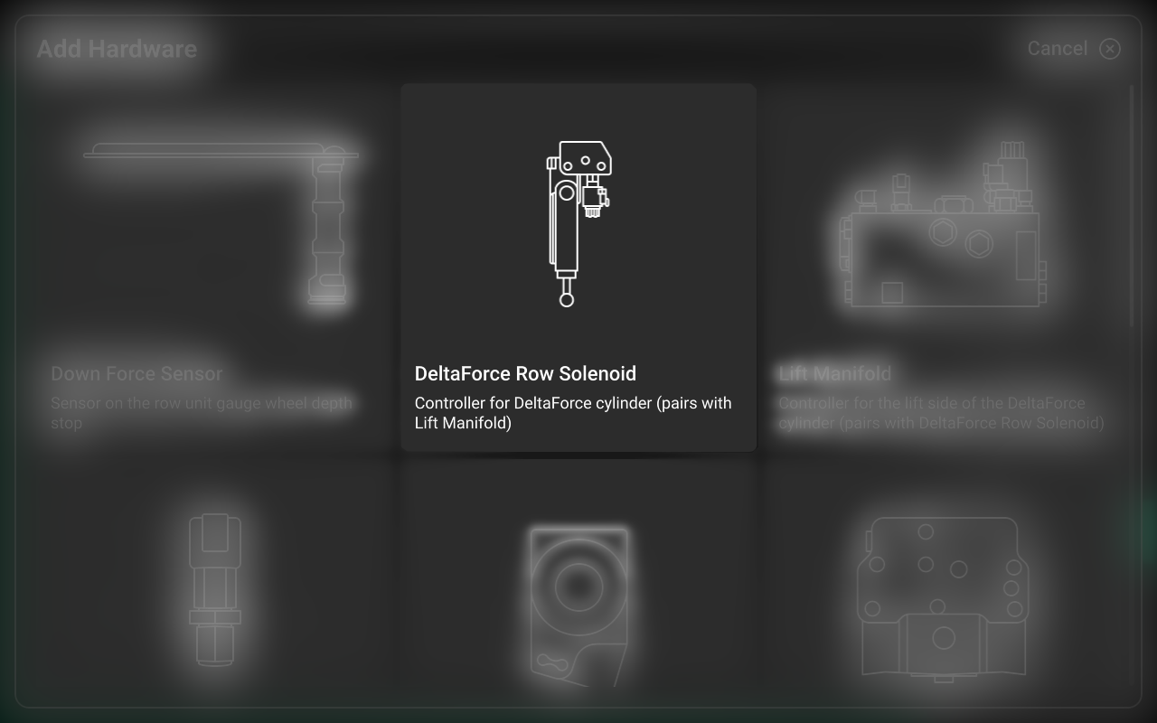
Press Add [System Name] Hardware + and select DeltaForce Row Solenoid from the popup to open the DeltaForce Row Solenoid hardware setup wizard.
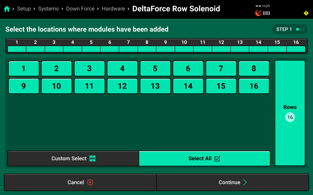
On Step 1, press each row that has a DeltaForce Row Solenoid installed or press Select All in the lower right, then press Continue.
On Step 2, use the left window to Custom Select or Select All Rows, then use the right window to change the desired setting. Press Save and Finish to exit setup.
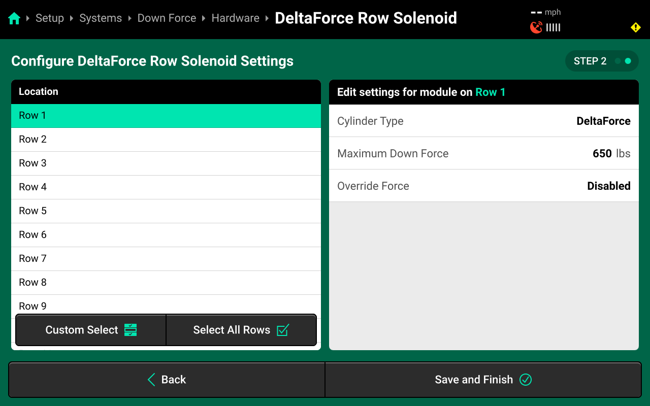
Cylinder Type
- This will default to DeltaForce Cylinder.
Maximum Down Force
- This allows the user to limit the Maximum Applied Down Force.
This should not be changed unless directed by Product Support.
Override Force
- This function will allow the user to enable or disable a static applied Down Force.
If Override Force is enabled this will ignore the load sensor weight readings and command a static target to all DeltaForce Row Solenoids, and should only be used as a limp home method in the event of multiple load sensor failure.
Lift Manifold
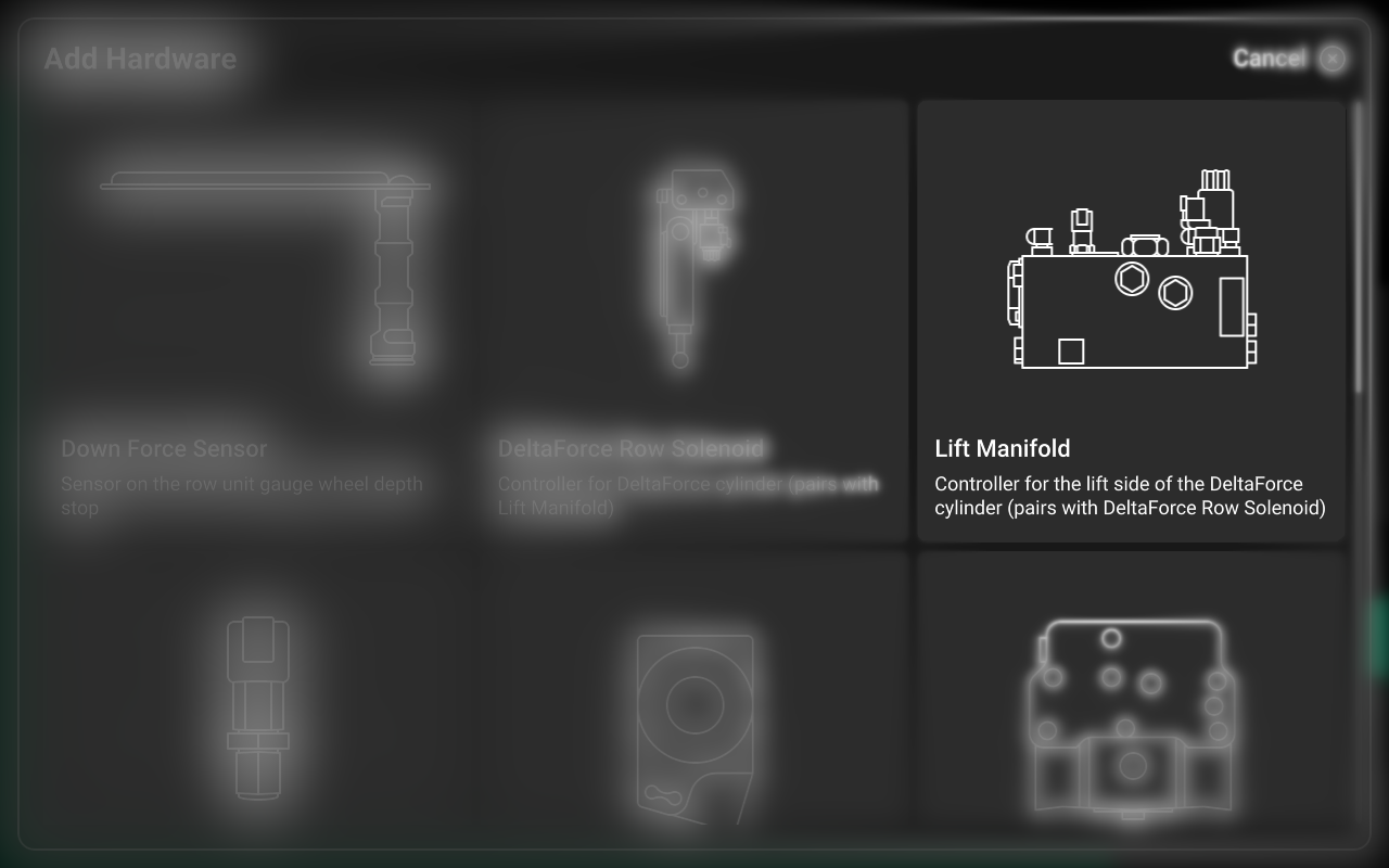
Press Add [System Name] Hardware + and select Lift Manifold from the popup to open the Lift Manifold hardware setup wizard.
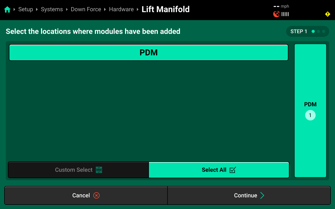
On Step 1, press PDM or press Select All in the lower right, then press Continue.
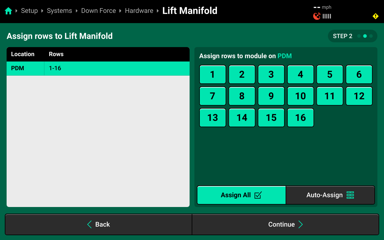
On Step 2, use the right window to Select All Rows then press Continue.
On Step 3, use the right window to change the desired setting. Press Save and Finish to exit setup.

Maximum Lift Force
- This allows the user to limit the Maximum Applied Lift Force.
This should not be changed unless directed by Product Support.
Override Force
- This function will allow the user to enable/ disable s static applied Lift Force.
If Override Force is enabled this will ignore the load sensor weigh readings and command a static lift target to every row cylinder, and should only be used as a limp home method in the event of multiple load sensor failure.
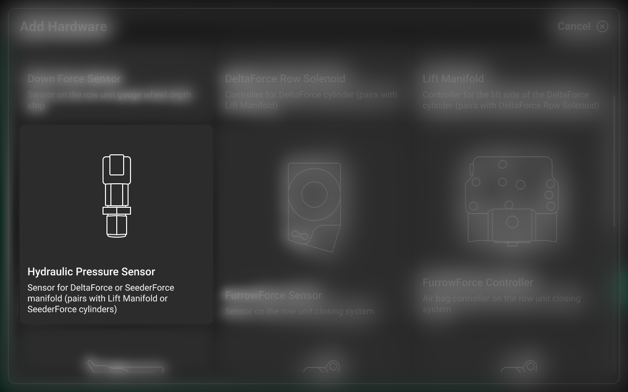
Hydraulic Pressure Sensor
Press Add [System Name] Hardware + and select Hydraulic Pressure Sensor from the popup to open the Hydraulic Pressure Sensor hardware setup wizard.
On Step 1, press PDM or press Select All in the lower right, then press Save and Finish to exit.

All configured hardware devices will appear on the Hardware screen for each system. Press the three dots on each device to delete it, or press Edit Locations to run through the setup wizard again.
After configuring a hardware device, that device will appear under Hardware for that system in the Navigation Menu. Press any hardware device to view the settings from the final step of the setup wizard.

Accessing Hardware Settings
Hardware settings are divided into Install Settings, which are typically adjusted during initial setup, and Operation Settings which may be adjusted multiple times per season / year.
Install Settings are accessible on the final step of each hardware setup wizard, and on the specific system hardware screen after that hardware device is added (see tip in the previous section).
Operation Settings are accessible from the left window of the specific system screen after the hardware device is added. It may be necessary to scroll to view all Operation Settings.
System Settings
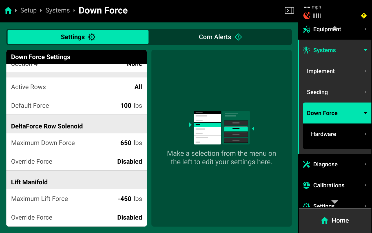
After hardware setup is complete, press [Down Force System Name] in the Navigation Menu to adjust system settings.
Additional options will be available after hardware setup is complete. View all options by scrolling on the list.
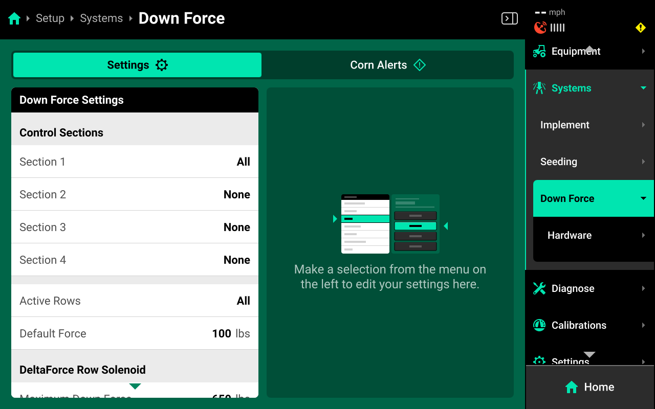
Select a setting in the left window and modify the setting using the right window.
- Control Sections : Used to set up different Control sections. Select a preset number of rows for each section or use Custom to assign rows manually. Control sections are system-specific. The rates for each control section are adjustable individually or collectively using the system Control widget on the home screen.
- Active Rows : Sets the active rows for the system. System hardware on any rows not set to active will be deactivated. This setting will typically not be adjusted. To adjust active rows (e.g. when switching from corn to beans on a split-row planter), use Active Rows in the planter profile at Setup > Equipment > Planter.
- Default Force : Sets the out-of-prescription Down Force Target.
Alerts
Use the tab at the top of [Down Force System Name] to view the crop-specific alerts for the Down Force System. Some alerts are adjustable by default, others require the corresponding hardware to be added first. It is advised to add all system hardware before configuring alerts for ease of use. All crops have the same default alert settings, but any changes made will be saved to the specific crop. Press Restore Defaults at the bottom to reset crop alert settings.
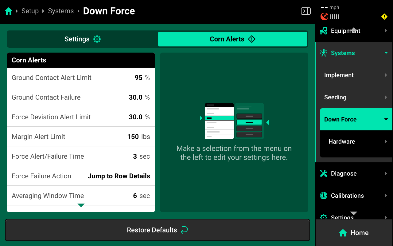
Some alerts contain both Alert and Failure limits. The 20|20 will display a popup notification when alert limits are reached, and will perform the action selected for Failure Action when failure limits are reached.
For Down Force systems, the thresholds for all Alerts correspond to the ground contact value that each down force sensor is reading.
Use the left window to select an alert and the right window to modify its parameters.
- Ground Contact Alert Limit : Sets the percent of lose of ground contact at which the 20|20 will deliver an alert.
- Ground Contact Failure : Sets the percent of lose of ground contact at which the 20|20 will deliver an failure alarm.
- Force Deviation Alert Limit : Sets the percent of difference from applied force to the commanded target at which the 20|20 will alert.
- Margin Alert Limit : Sets the percent of Margin at which the 20|20 will alert.
- Force Alert/ Failure Time : Sets time in seconds until a failure or alert will populate.
- Force Failure Action : Determines what action the 20|20 will perform when failure thresholds are reached.
- Jump to Homepage : The 20|20 will go the Home Screen when the threshold is reached.
- Jump to Row Details : The 20|20 will go to the Row Details screen when the failure threshold is reached.
- No Action : The 20|20 will not take any immediate action when the failure threshold is reached.
- Average Window Time: This is the rolling average in seconds of data collected to display metrics.
- Force Adjustment : Sets the value of how pounds of down force you can increase/ decrease on the control widget.
Calibrations
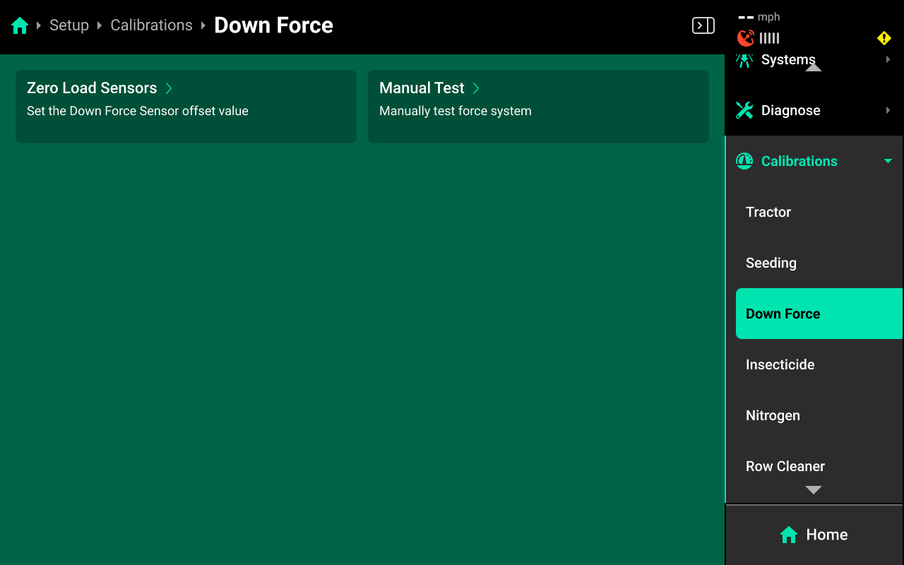
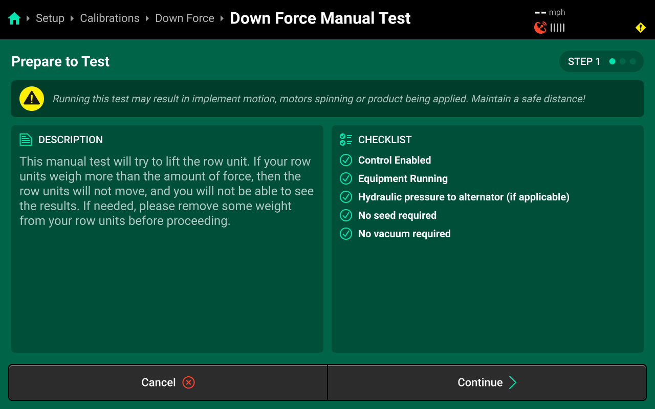
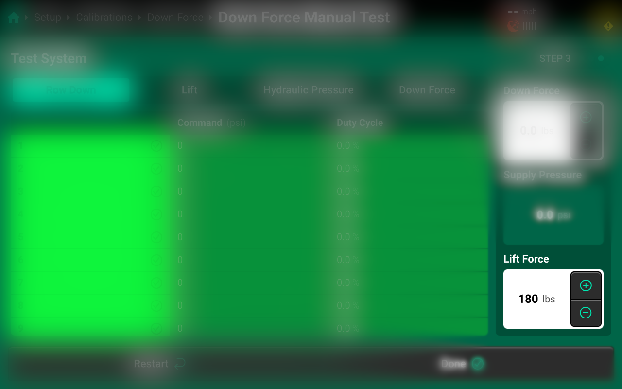
Manual Test
Navigate to Setup > Calibrations > [Down Force system name] and press Manual Test to access the Down Force manual test. This calibration will test the Down Force system for correct operation, and should be performed on all new installations and at the start of each season. This calibration will lift and lower the row units.
Ensure all conditions in the checklist are met and press Continue.
This test will lift and lower the row units, ensure no person of object is in the way of row unit travel.

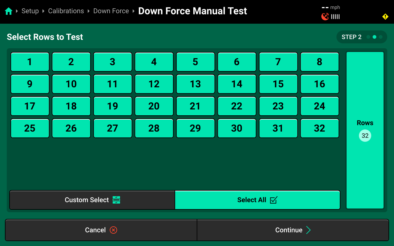
Press Select All to run calibration on every row or make a custom selection using the table in the center, then press Continue.
Even if you do not select all rows, since DeltaForce is system wide lift all rows will lift when there is a lift command in the manual test.
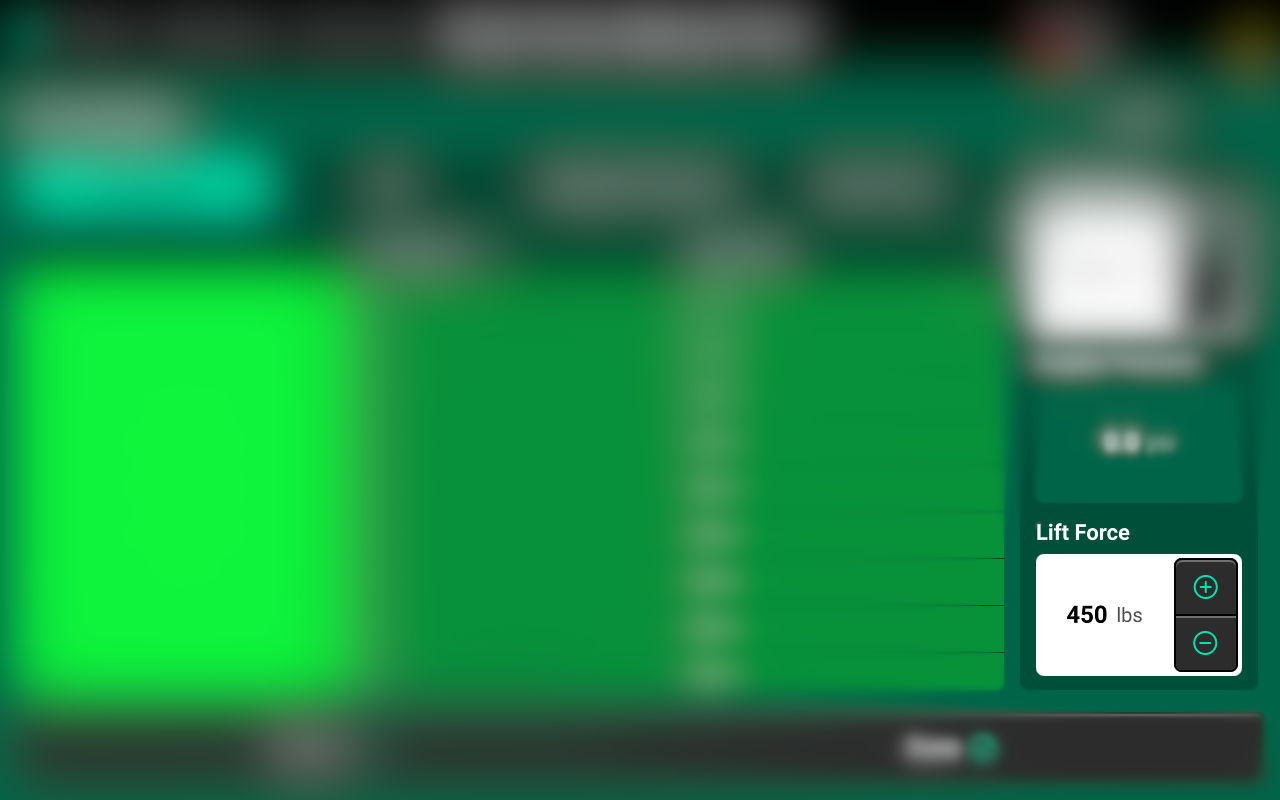
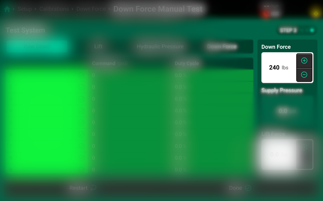
Step 1 Testing the Lift Circuit
- Start by Pressing the Lift Force Command + button until you get to 450 Ibs.
- Row Units should lift on there own at this point or with slight assistance.
Switch to the Lift Tab to view Command (PSI) and Duty Cycle.
Step 2 Testing the Down Circuit
- Leave the Lift Force Command at 450 Ibs
- Start by Pressing the Down Force Command + button until you get to 650 Ibs.
- Row Units should return to the lowered state.
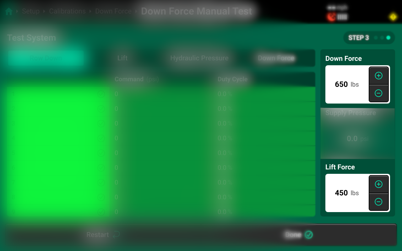
Step 3 Test is complete (All row units should have lifted and lowered for a successful test)
- Press the Lift Force Command - button until you get to 0 Ibs.
- Press the Down Force Command - button until you get to 0 Ibs.
- Click Done to complete test.
Zero Load Sensors
Navigate to Setup > Calibrations > [Down Force system name] and press Zero Load Sensors to access the Zero Load Sensors Calibration. This calibration will Calibrate the New Load Sensors Zero, and should be performed on all new installations and at the start of each season.
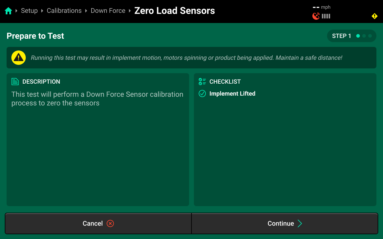
Ensure all conditions in the checklist are met and press Continue.
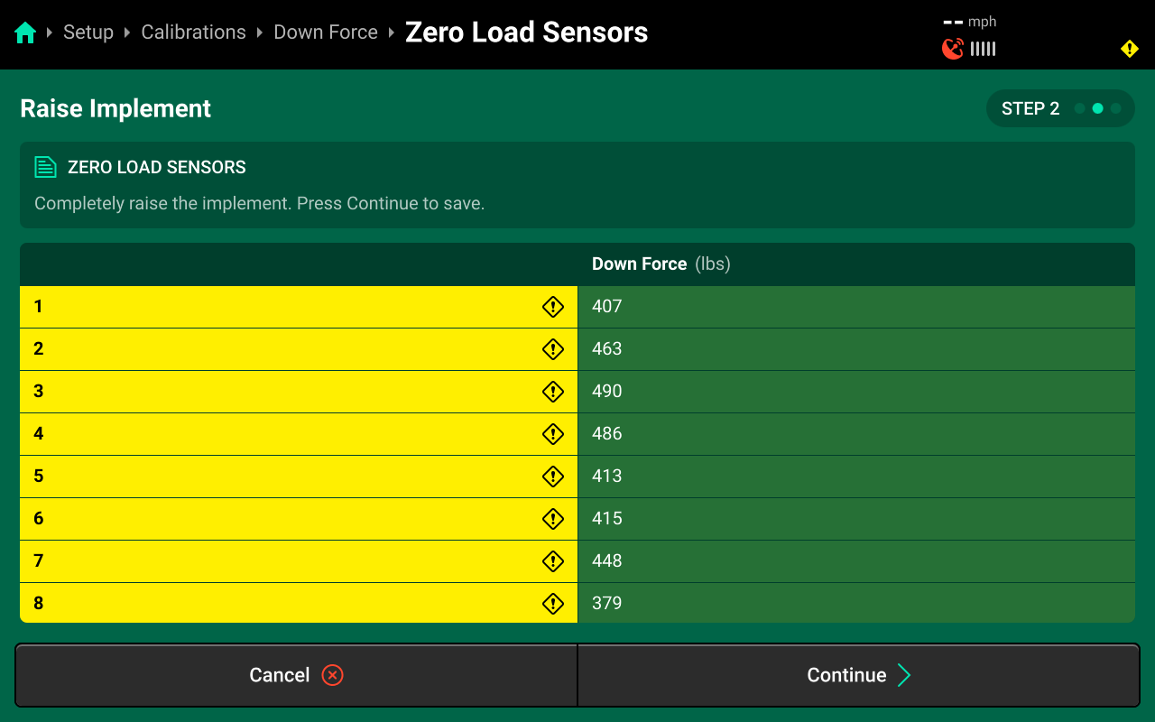
Step 1 When the implement is completely raised press Continue
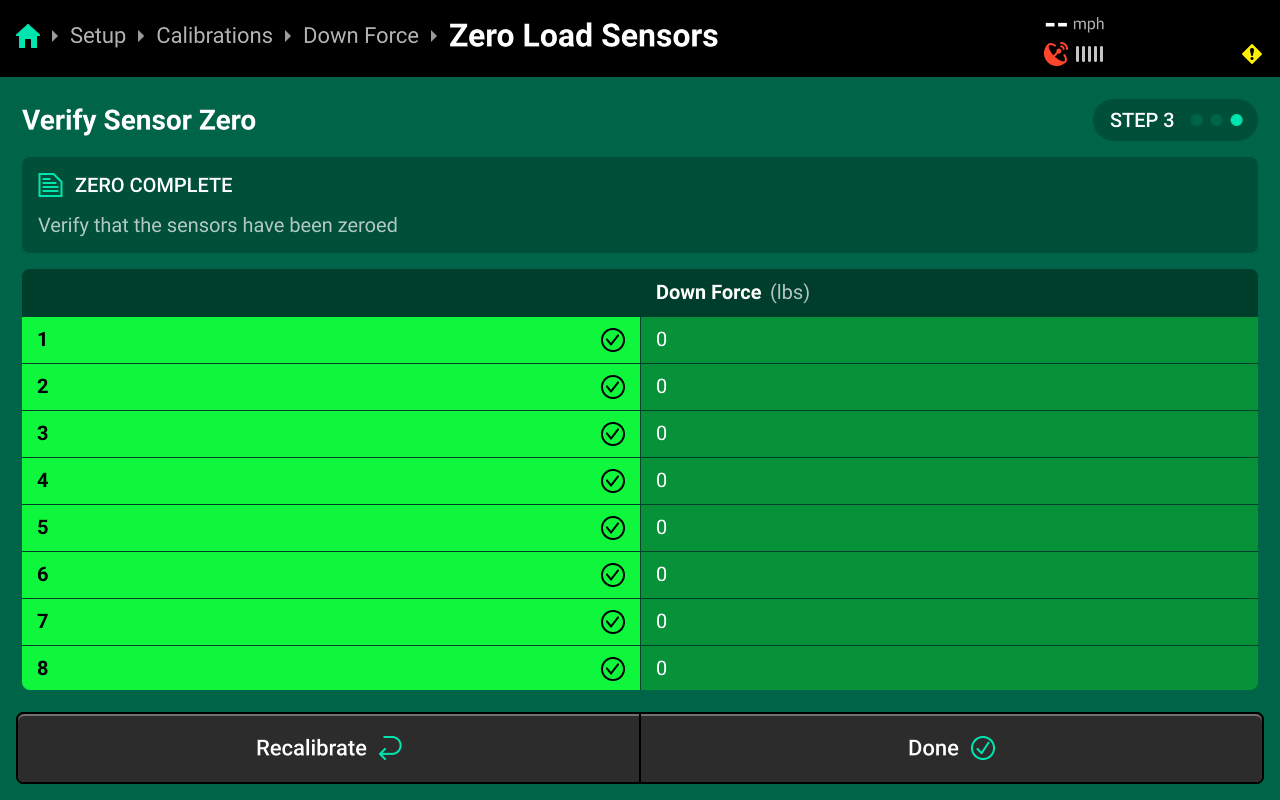
Step 2 The Calibration is complete verify that all load sensors hold +/- 5Ibs from zero.
New Install (Air Purge)
Navigate to Setup > Calibrations > [Down Force system name] and press Manual Test to access the New Install Calibration. This calibration will purge air from the Down Force system, and should be performed on all new installations and upon replacement of any hydraulic component. This calibration could lift and lower the row units.
During this test the cylinder will extend and retract. The Bottom cylinder pins must be unpinned and secured to not contact with any row unit obstruction during this test. If replacing one cylinder unpin the row on either side then do this calibration.
For a successful test verify that all cylinders fully extended and retracted a minimum of 3 times. In certain cases, you will have to repeat this process up to 3 times.
Ensure all conditions in the checklist are met and press Continue.
Press Select All to run calibration on every row or make a custom selection using the table in the center, then press Continue.
Even if you do not select all rows, since DeltaForce is system wide lift all rows will lift when there is a lift command in the manual test.

Step 1 Purging the Down Circuit
- Start by Pressing the Down Force Command + button until you get to 240 Ibs, let the system hold that command for 10 seconds.
- Then press the - button until the weight reading is back at 0 Ibs.
Step 2 Purging the Lift Circuit
- Start by pressing the Lift Force Command + button until you get to 180 Ibs, let the system hold that command for 10 seconds.
- Then press the - button until the weight reading is back at 0 Ibs.
Switch to the Lift Tab to view Lift Command (PSI) and Duty Cycle.
Step 3 Repeat steps 2 & 3, three times, or until Air Purge is satisfied.
Diagnostics
Diagnose Menu Overview
The Diagnose Menu is used to identify and troubleshoot hardware device failures and configuration issues in the 20|20.
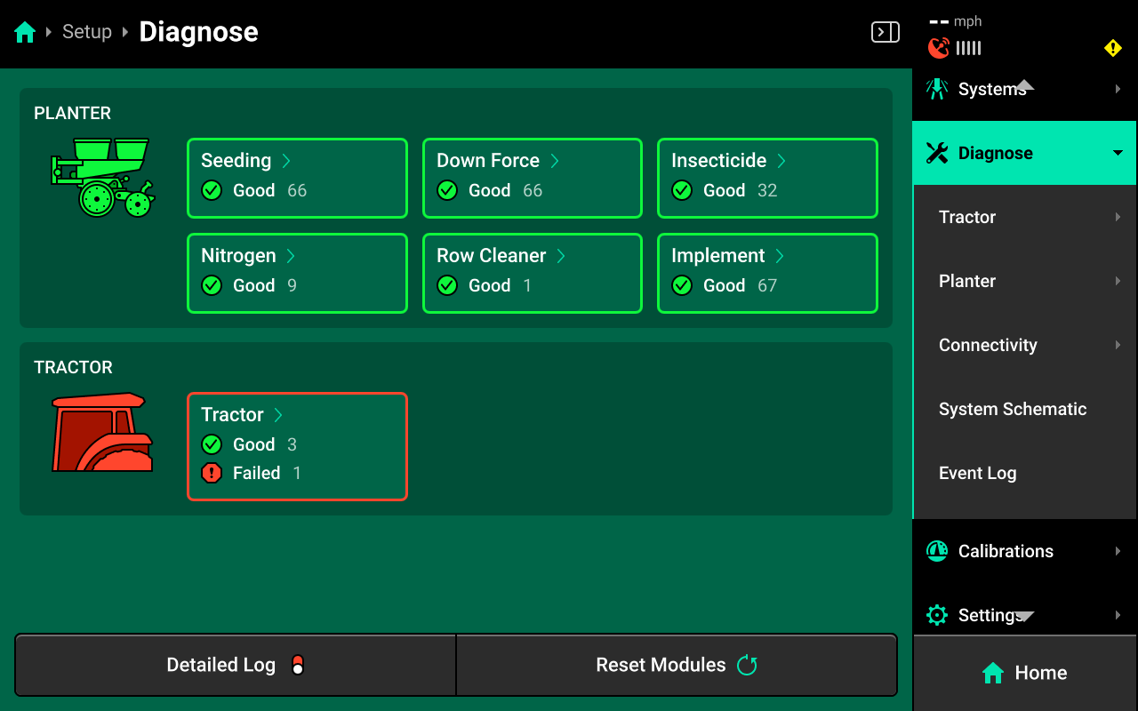
Use the following colors to determine device status on the Diagnose screen.
- Green : Device is working correctly. Communications are good.
- Yellow : Device or sub-component is not 100% functional.
- Red : Device has failed, or is expected and not detected.
- White : Device is detected but not expected.
- Black : Device has been disabled by the user.
- Grey : Device is finishing detecting or unreachable.
- Teal : Device is updating firmware.
Press Reset Modules at the bottom and confirm on the popup to break and reestablish all CAN communication and daisy chain identification. This function is often used as a troubleshooting tool for communication issues.
Due to programming changes for sprayer and seeder compatibility, after pressing Reset Modules or power cycling in software versions 2023.1.0 and above, if a daisy chain break is present in the physical harnessing, all components after the daisy chain break will display red on the diagnose page. The break must be addressed before implement functionality is restored.
DeltaForce Diagnostics
To view DeltaForce diagnostics, navigate to Setup > Diagnose, then press anywhere on the Planter or press Planter under Diagnose in the Navigation Menu.
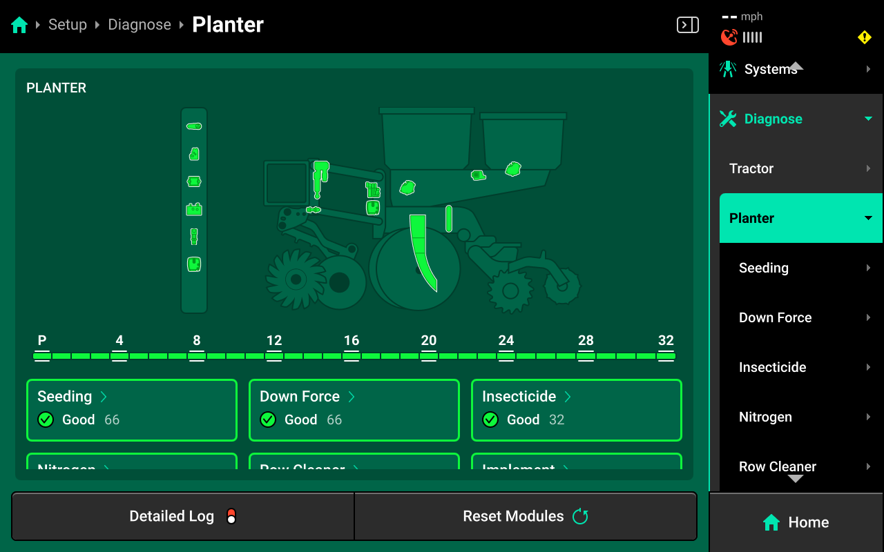
Next, select [Down Force System Name] in the center, or press [Down Force System Name] under Planter in the Navigation Menu.
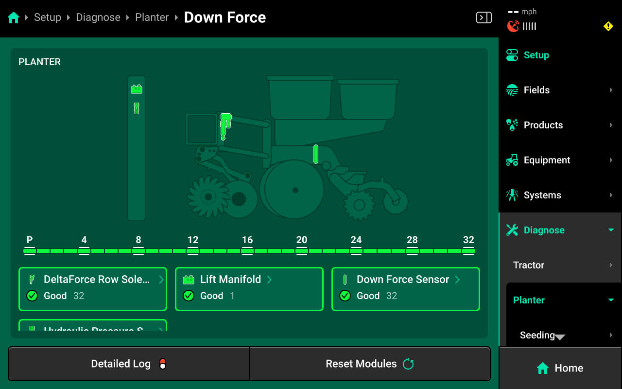
DeltaForce Row Solenoid
Press DeltaForce Row Solenoid in the center or in the Navigation Menu to view detailed diagnostics for DeltaForce Row Solenoid.
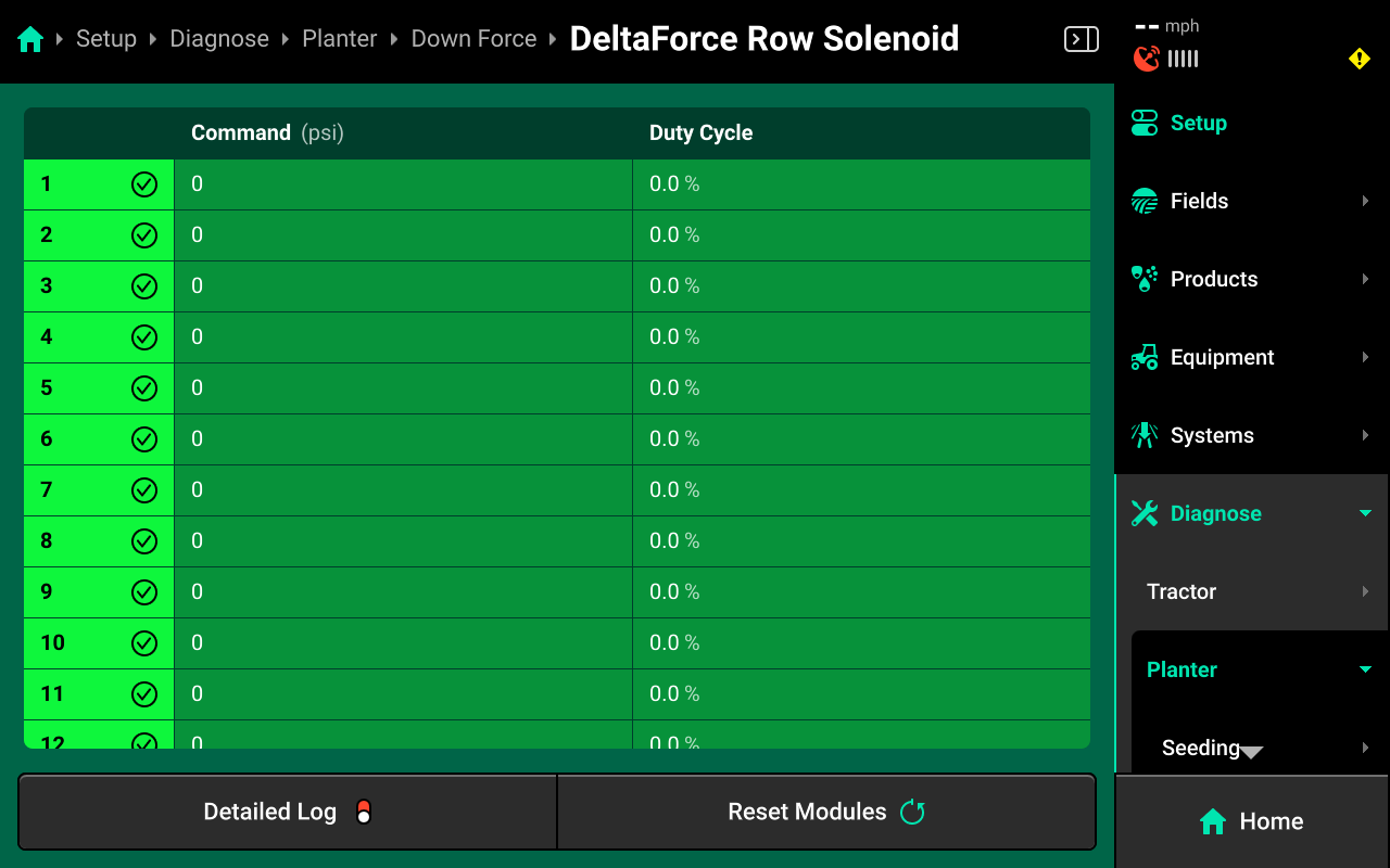
- Command (psi): commanded Down Force PSI of each DeltaForce Cylinder
- Duty Cycle: displays the DeltaForce Row Solenoid output over the operating range, 0-100%.
Lift Manifold
Press Lift Manifold in the center or in the Navigation Menu to view diagnostics for the lift manifold.
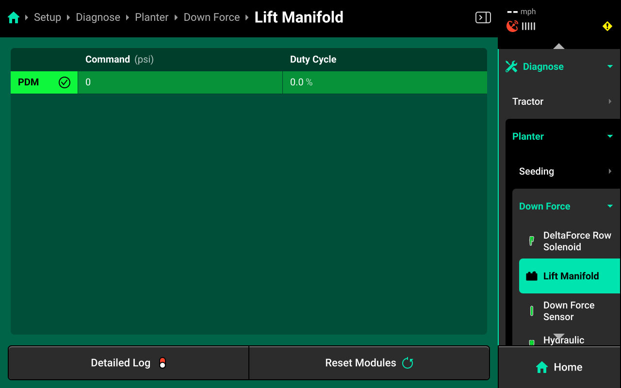
- Command (psi): commanded Lift Force PSI of the Lift Manifold
- Duty Cycle: displays the Lift Manifold output over the operating range. 0-100%.
Down Force Sensor(s)
Press Down Force Sensor in the center or in the Navigation Menu to view diagnostics for the Down Force Sensor(s).
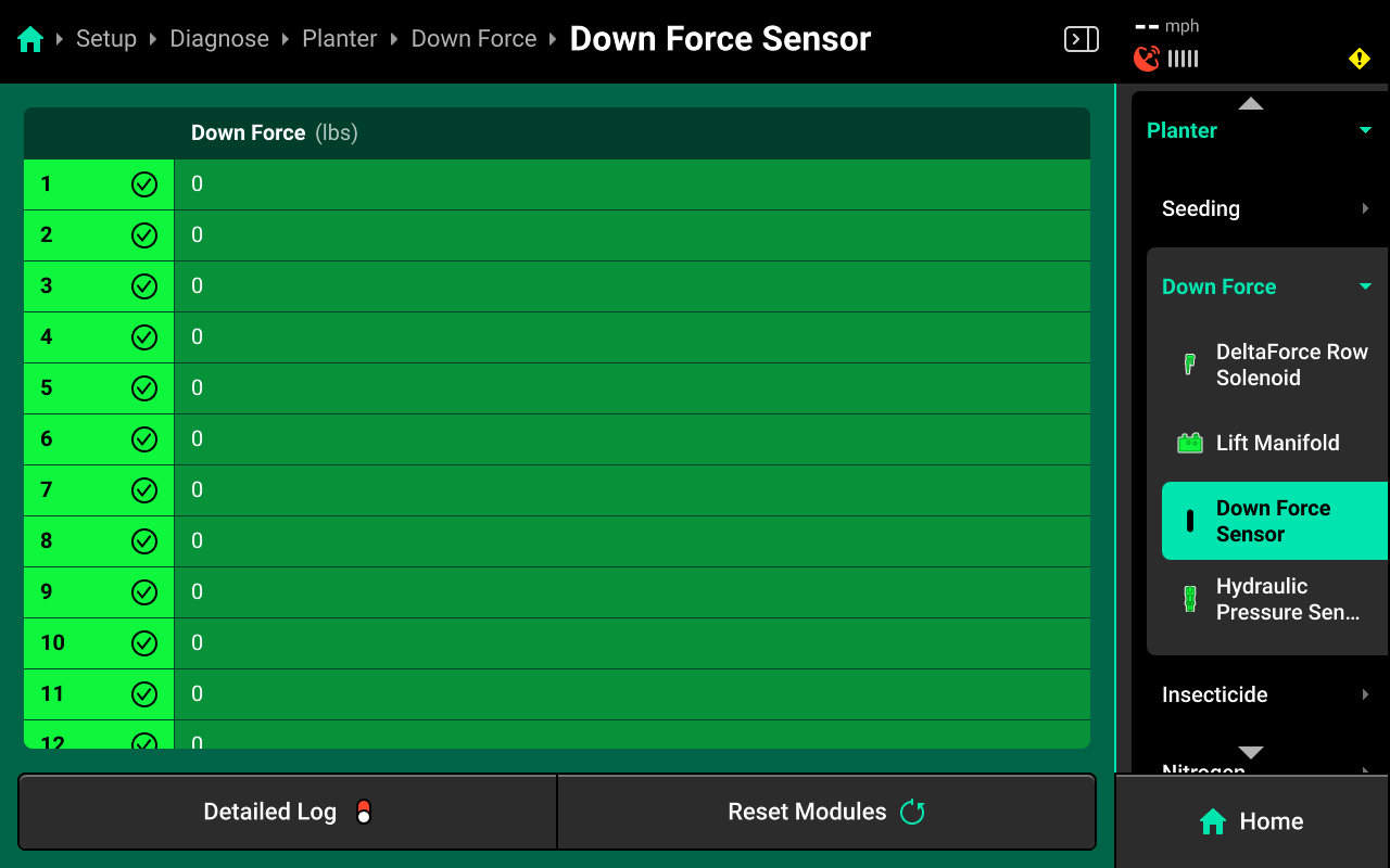
- Down Force (Ibs): displays load sensor weight reading in Ibs.
Hydraulic Pressure Sensor
Press Hydraulic Pressure Sensor in the center or in the Navigation Menu to view diagnostics for the Hydraulic Pressure Sensor.
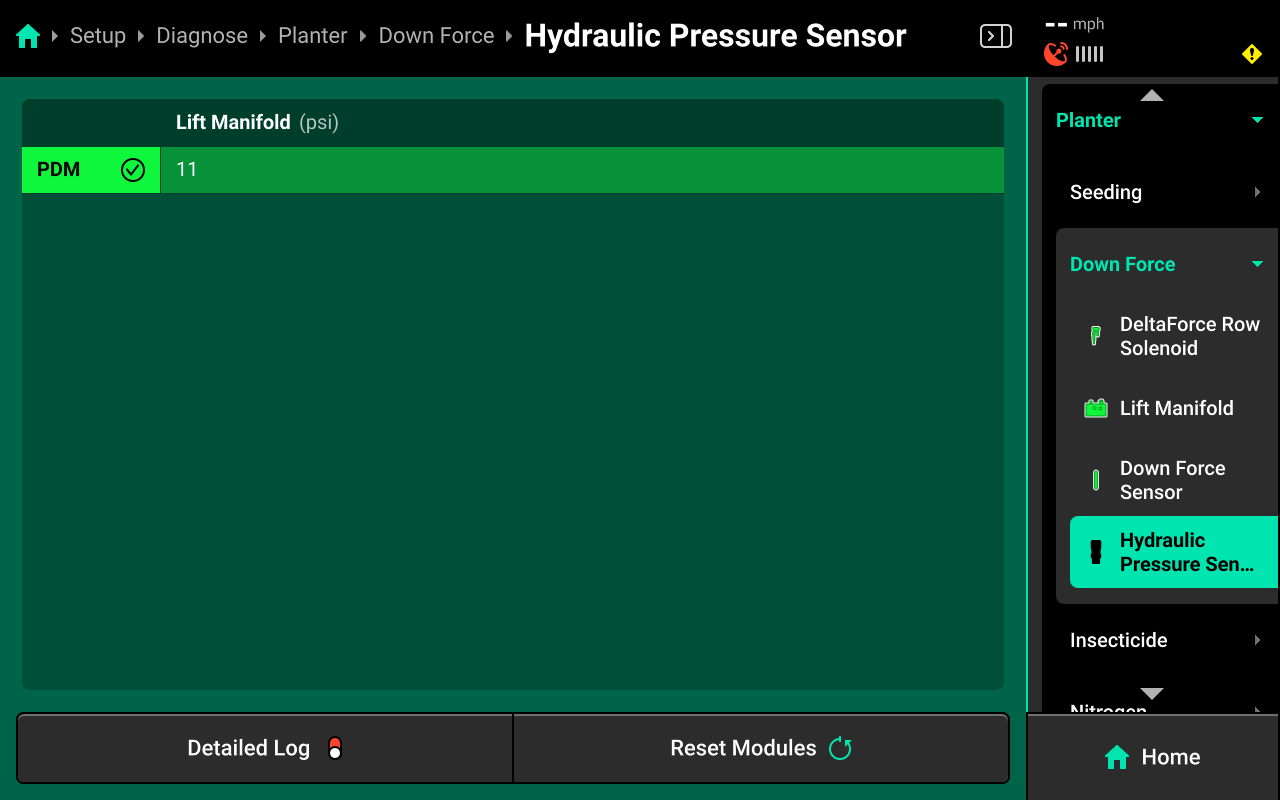
- Lift Manifold: displays system PSI.
Common Troubleshooting Issues
Diagnose screen
Verify hardware health using the color key provided at the beginning of this section. Common issues include:
-
Yellow Down Force System:
- Load Sensors Zero calibration not complete.
- Sensor Type is incorrect (Setup > Systems > Down Force > Hardware > Down Force Sensor).
- Row Unit Selection is incompatible with Load Sensor (Setup > Equipment > Planter > Row Unit Type).
-
Red Down Force System:
- Damaged Load Sensor or Row Solenoid.
- Disconnected hardware.
- Misconfigured system setup.
-
White Down Force System:
- Incomplete system setup.
Pressure Diagnostics
Hydraulics Engaged
| Location | Pressure |
|---|---|
| Cylinder P-Port | 2250-3000 PSI |
| Cylinder R-Port | 0 PSI |
| Cylinder L-Port | 0 PSI |
| Lift Manifold PG-Port | 2250-3000 PSI |
| Lift Manifold RG-Port | 0 PSI |
| Lift Manifold LG-Port | 0 PSI |
Manuel Test while commanding 650 lbs down & 450 lbs lift
| Location | Pressure |
|---|---|
| Cylinder P-Port | 2250-3000 PSI |
| Cylinder R-Port | 0-100 PSI |
| Cylinder L-Port | 2250-3000 PSI |
| Lift Manifold PG-Port | 2250-3000 PSI |
| Lift Manifold RG-Port | 0-100 PSI |
| Lift Manifold LG-Port | 2250-3000 PSI |