20|20 Gen 3 Operator's Guide
This guide is intended for use with a Gen 3 20|20 with version 2026.0.0 software or other 2026.0 variant software installed. Guides for older versions of Gen 3 20|20 software may be found at cloud.precisionplanting.com.
 Contents
 General Overview
This guide contains information on navigating the 20|20 Gen 3 monitor, understanding the information that it displays, and setting up basic equipment and systems. For detailed troubleshooting or specific Precision Planting product information, refer to all specific product operator's guides, or contact Precision Planting Product Support.
Hardware
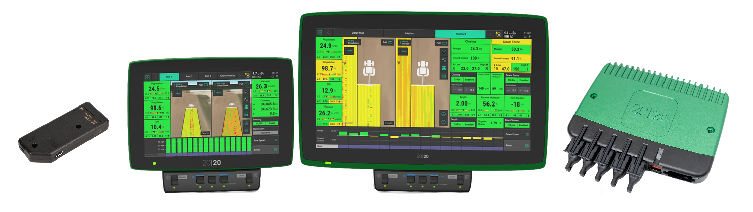
The 20|20 consists of a Display Base Module [DBM] connected to at least one Display by an Ethernet cable. Other Ethernet devices may also be connected to the DBM.
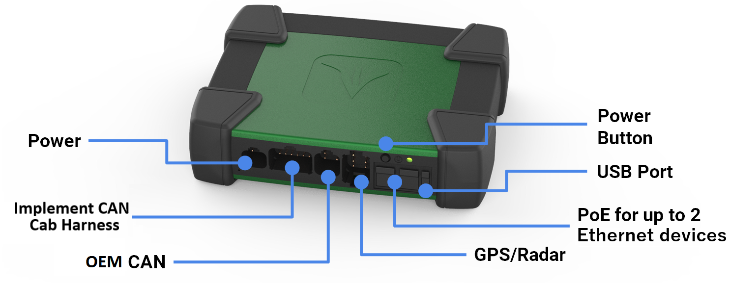
The DBM Power over Ethernet [PoE] ports require a Shielded Twisted Pair [STP] CAT6 Ethernet cable to connect an Ethernet device to the DBM. The different Ethernet devices that may be connected to the DBM are the 10” display, the 16” display, the FieldView Module, and the Ethernet Switch.
Do not connect an Ethernet cable from an Internet access point to the Ethernet port on the DBM. Doing so will crash the access point. See Connecting to Hardwired Internet for information on connecting the 20|20 to an Internet access point.
Indicator Light Overview
Each Ethernet device utilizes a light to indicate device status. Use the following table to determine the status indicated by the light on the corresponding device.
| Color | DBM | Display | FieldView Module | Ethernet Switch |
|---|---|---|---|---|
| Green | Powered On / Connected | Powered On / Connected | Powered On / Connected | Powered On / Connected |
| Solid White | Powering On | N / A | Downloading Software | Powering On |
| Blinking White | Firmware Updating | N / A | N / A | Firmware Updating |
| Solid Yellow | Preparing to Update Software | Initializing | Initializing | Initializing |
| Blinking Yellow | Software Update in Progress | Software Update in Progress | Software Update in Progress | Software Update in Progress |
| Blue | N / A | N / A | Powered on, no connections established | N / A |
| Purple | User must Power Cycle System | N / A | FieldView Cab App not Connected | User must Power Cycle System |
| Red | N / A | Powering On | Powering On | N / A |
| Blinking Red | Failure - Contact Support | N / A | N / A | Failure - Contact Support |
Older versions of software displayed a blue LED on the DBM when a display and / or CCM was not connected. This light is no longer used in versions 2023.1.0 and newer.
Powering On / Off
The 20|20 requires 12 volts of key switched and constant power. Connect the display to the DBM, and the DBM to the power supply. If connected to a tractor or cab, turn the key to the on or run position. Press the DBM power button to the on position. To power the system off, press the DBM power button to the off position or key the tractor / cab off.
User License Agreement
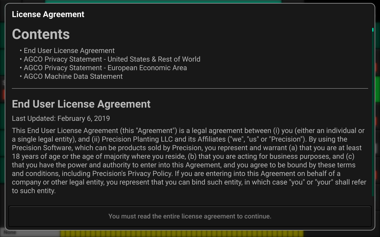
Once the 20|20 has booted up, read and agree to the User License Agreement to use the 20|20. Agreement is required on first boot up, after a Delete All is performed, or when major software updates are completed.
If this system is being set up for a third party, reset the agreement to appear on next startup so the end user agrees to the document. Navigate to Setup > Settings > About, select Agreements and press Reset EULA.
Cab Control Module
All Precision Planting control products require a Cab Control Module
[CCM] to be installed below the display. The CCM is connected using
an RJ11 port located on the back of the display. If two displays are
being utilized, only one display of the user’s choice may have a CCM
installed. The CCM will be auto-detected when connected properly.
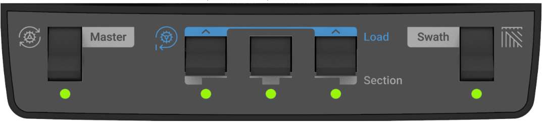
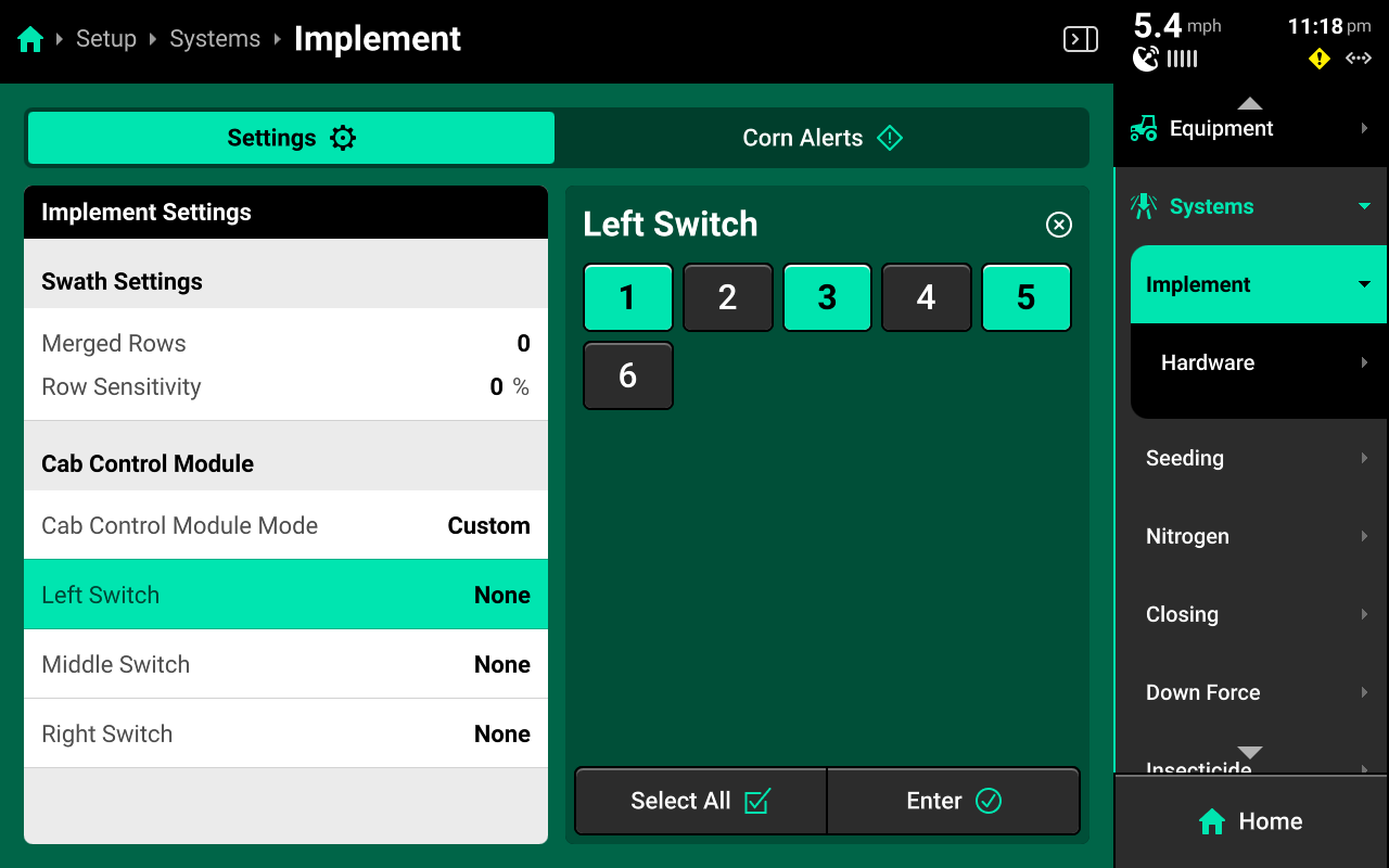
The switch on the left-hand side is the Master Plant switch. For all control products to function the Master Plant switch must be in the up position. If it is in the down position, all control products will immediately be disabled. The three switches in the middle are swath section switches. Toggle these to the down position to swath off a rate section. If these switches are in the down position, the rows assigned to the switch will be shut off. The rows assigned to each switch may be configured by navigating to Setup > Systems, selecting the default Implement system, changing Cab Control Module Mode to Custom, and selecting a preset or custom number of rows to each switch. See CCM Settings for more details.
The left and right swath section switches are also used to Autoload any systems which have the auto load function enabled. Raise both switches up for one second to load systems. Systems with defaults rates entered and autoload enabled will dispense product. This allows product to immediately be dispensed when beginning to plant / apply. To continue autoloading, lift and hold both switches. Product will continue to dispense as long as the switches are held up.
Safety Warning
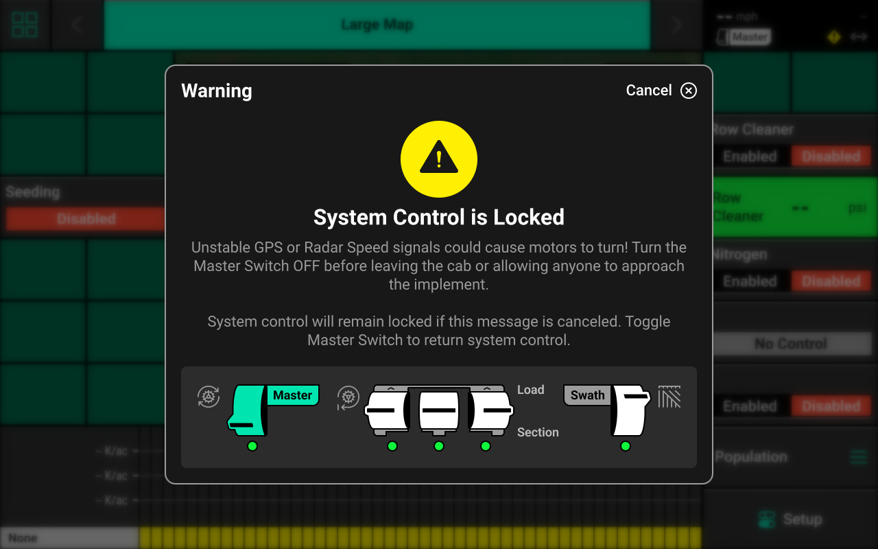
If any control product is configured on the 20|20 display, the system will require a CCM and will prompt the user to toggle the Master Plant switch on the CCM before any control products may be used. This warning is triggered any time the system is booted up, and when the system has traveled for more than half a mile. If a CCM is not installed, press cancel to bypass this warning. No control systems will operate until the Master Plant switch is toggled. The ![]() Icon will be present in the top right of the 20|20 screen in the Status Center if the safety warning was bypassed and a control system is configured.
Icon will be present in the top right of the 20|20 screen in the Status Center if the safety warning was bypassed and a control system is configured.
 Home Screen
Overview
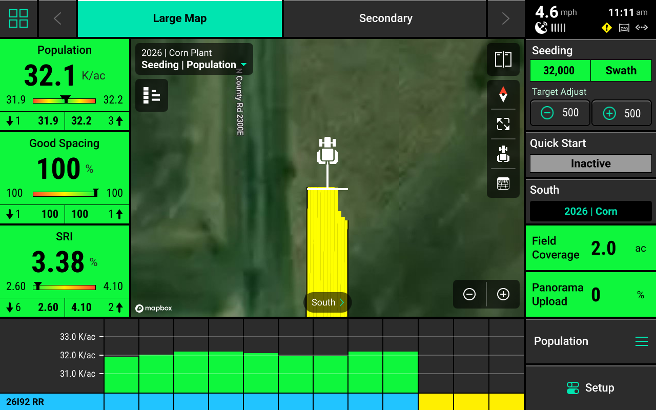
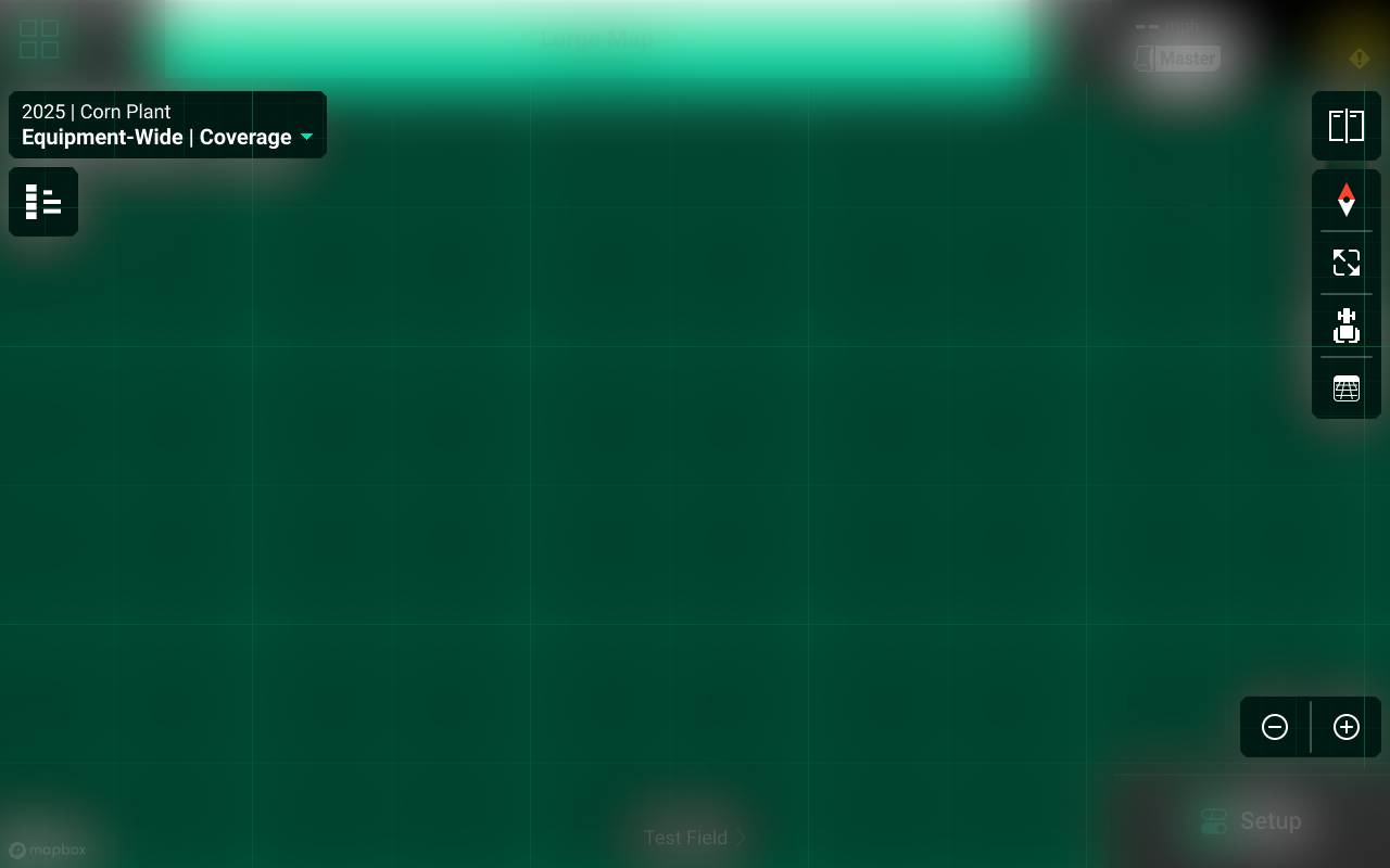
The Home Screen displays seeding and application data in an easy to read and navigate format. This information is presented as both metrics and high-definition maps. Additional screen configurations may be added and customized with different metrics, map sizes, controls, and bar charts. Screen configurations may be toggled between by pressing the arrows at the top of the screen.
Home Screen Layout Tabs
Tabs are located at the top of the screen that may be configured to quickly change the layout of the Home Screen. The only default tab layout is Large Map.
Up to eight total layouts may be configured and named. To configure new layouts, Press the Four Squares in the top left, then press Layout +.
Once new layouts have been added, pressing on a tab will change the layout of the home screen. Use the arrows or swipe left / right on the tabs to change which tabs are visible.
Any layout may be customized with different maps, controls, and metrics. See Customizing the Home Screen for more details.
Customizing the Home Screen
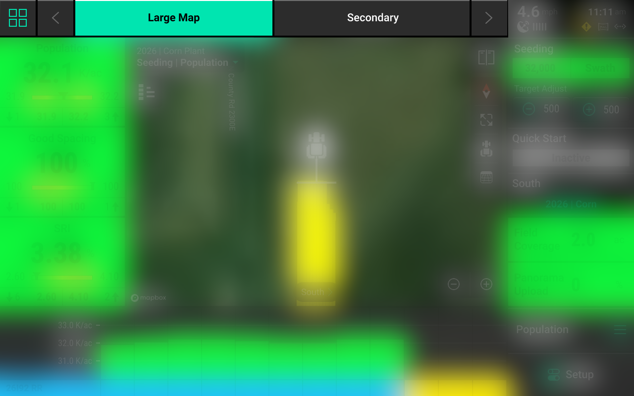
Press the Four Squares in the top left to enter Edit mode.
Only the active layout may be edited using this feature. To edit a different layout, press the Checkmark in the top left (while in Edit mode) to save current layout changes, then select a different layout. Press the Four Squares after selecting the desired layout to enter edit mode again.
Press Settings in the top right to rename or copy the active layout, or to reset all layouts. Press and drag on any layout to reorganize order.
After pressing the Four Squares, the Home Screen will be dimmed and overlaid with a grid which different control and metric widgets may be placed onto.
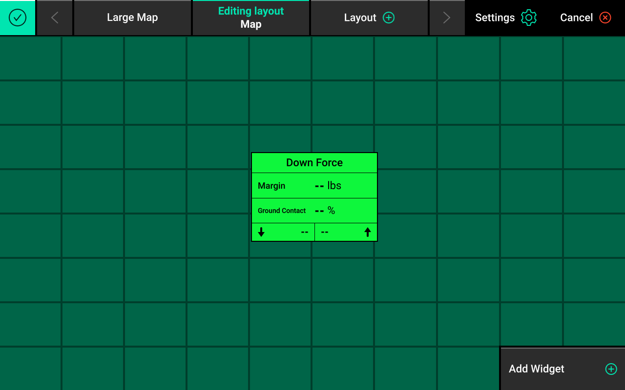
Press Add Widget + in the bottom right to add new widgets to the Home Screen.
There are four types of widgets: Metrics, Controls, Dashboard Minichart, and Maps.
Different sizes are available for each type of widget. Widgets are not always available in each size. The Map widget may be sized to any desired height and width.
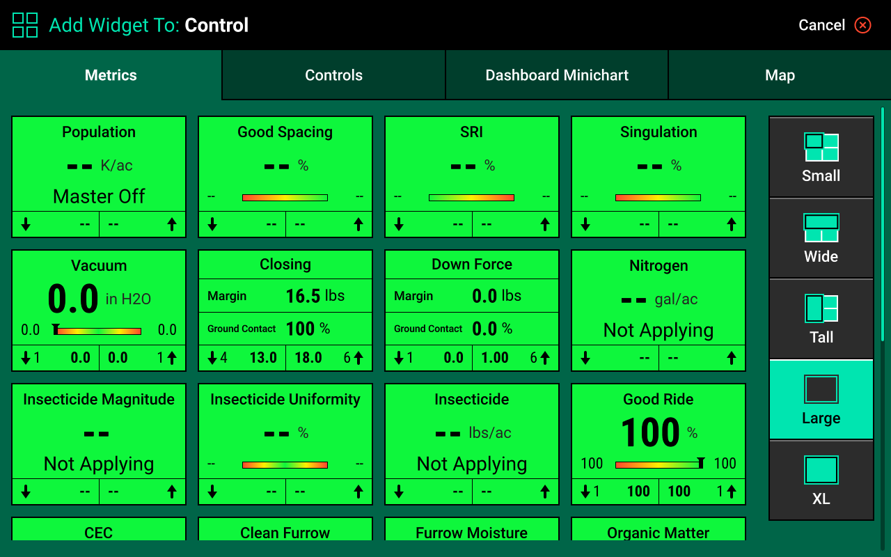
Every Precision Planting control or sensing product requires a Control widget to be placed on the Home Screen. The product will not function and cannot be calibrated until the corresponding widget is placed and enabled.
If any part of a new widget is placed on top of an existing widget, the entire existing widget will be removed.
After a widget has been set in place, press Add Widget + again to continue customizing the layout. After customization is complete, press the Checkmark in the top left to save the current layout.
Dashboard Mini-Chart and Metric Screen
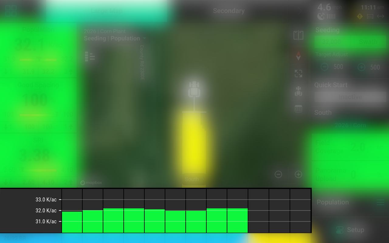
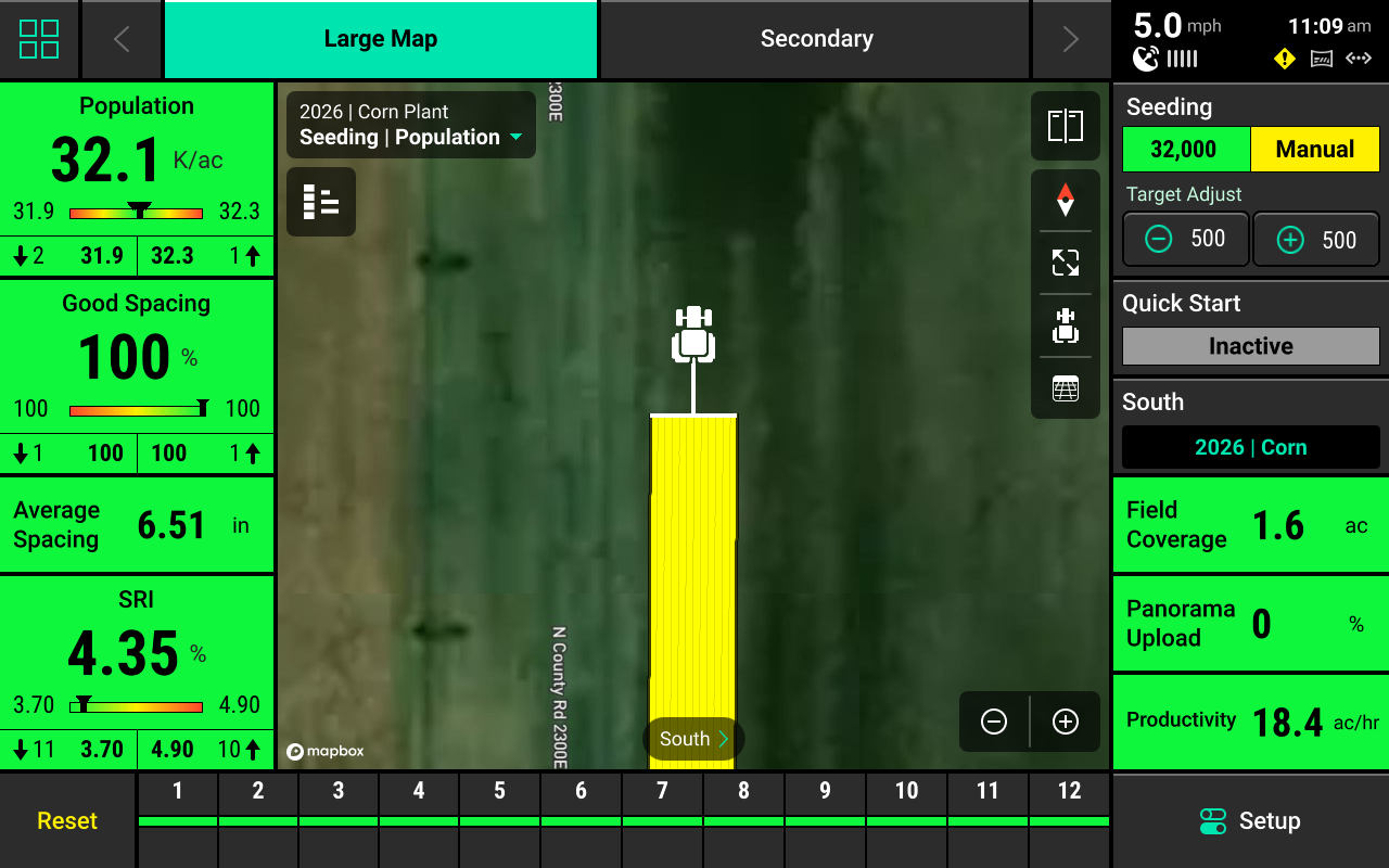
The Dashboard Mini-Chart [DMC] may only be placed at the bottom of the screen. The DMC displays a row-by-row bar chart for one of the metrics measured by the 20|20 for each row. Good row bars will be green, Alarm row bars will turn yellow, while Failure row bars will turn red. A scale showing numerical values is displayed in the lower right corner. See Alerts for more details on adjusting Alarm and Failure thresholds.
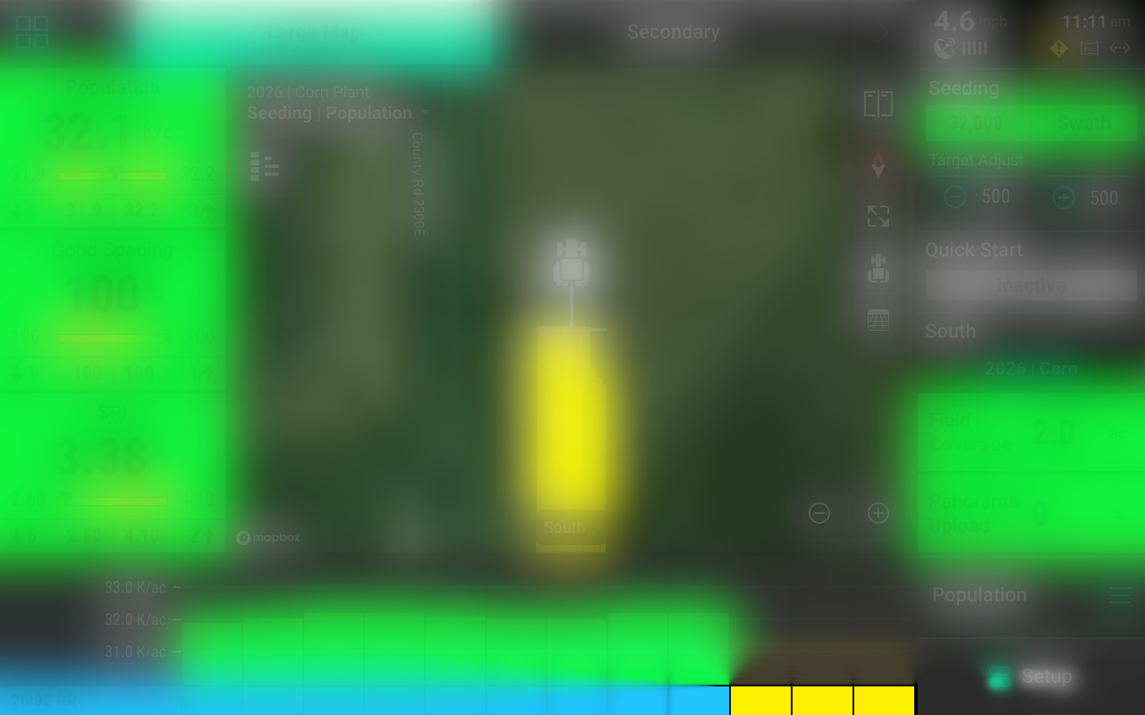
Rows that are swathed off will show yellow under the row bars on the bottom line of the DMC.
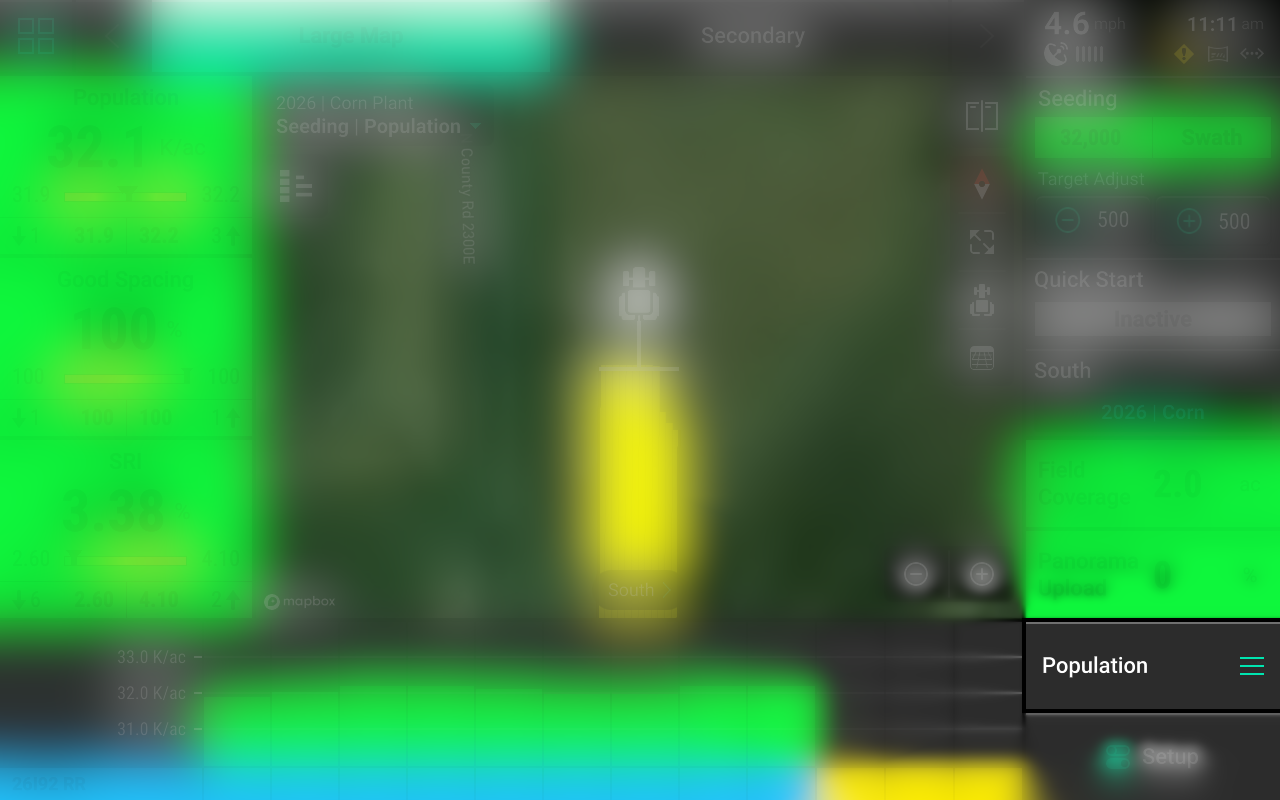
The name of the active metric shown on the DMC is displayed above the Setup button. To change the metric, press on the active metric name to open the Metric screen.
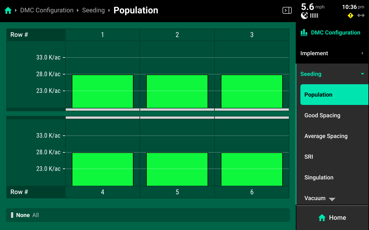
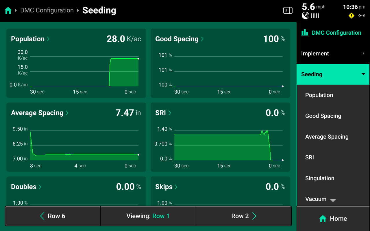
The Metric screen displays a more detailed row-by-row chart. Press any option on the right to view the row details screen for the selected system metrics. Scroll on the menu to view all available options. For applicable metrics, use buttons at the bottom of the screen to scroll between rows or to select a specific row.
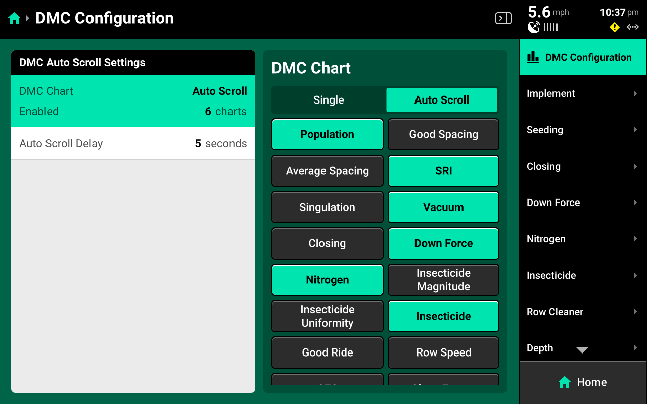
Press DMC Configuration in the upper right to toggle DMC Auto Scroll on or off, or to adjust the scroll frequency that the DMC will use when cycling between metrics. If Auto Scroll is set to single, change the displayed metric by selecting it in the table in the right window.
The Metric screen may also be accessed by pressing the corresponding widget (e.g. Singulation) on the home screen, or pressing the DMC directly.
Hybrids
Hybrids are displayed below the bar chart. The hybrid name in the lower left screen will alternate between hybrids if multiple are active.
Swath Control Bar
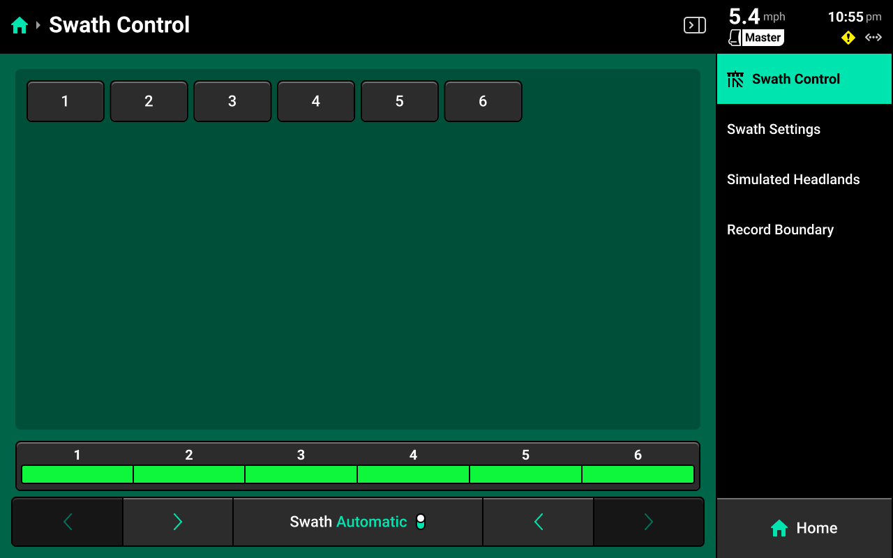
A Swath Control Bar may be added to the home screen instead of the DMC. The swath control bar may be used to manually swath on / off any rows for all systems which the 20|20 is controlling.
The Swath Control switch on the CCM must be in the Up position to enable manual swath control.
Press and hold on any row in the Swath Control Bar until it turns yellow to swath that row off. Press and drag across multiple rows after the initial row turns yellow to swath off multiple rows.
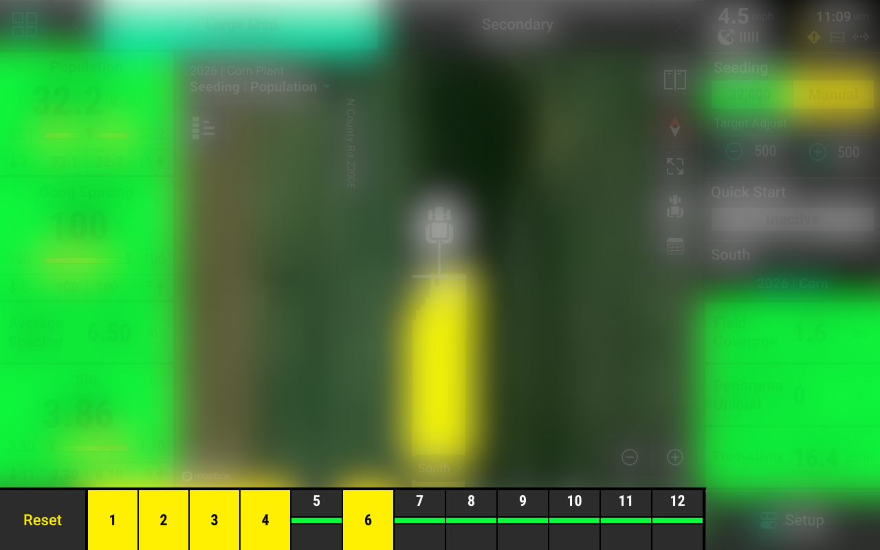
Swathing off any row manually will engage Manual Swath Mode. In Manual Swath Mode, the 20|20 will no longer swath off to boundaries or coverage. To return to Automatic Swath Mode, press Reset in the lower right corner.
The Swath Control Bar is also displayed on the Control screen for any control system, and on the Swath Control screen. See Swath Control Screen for more details.
Control Screens
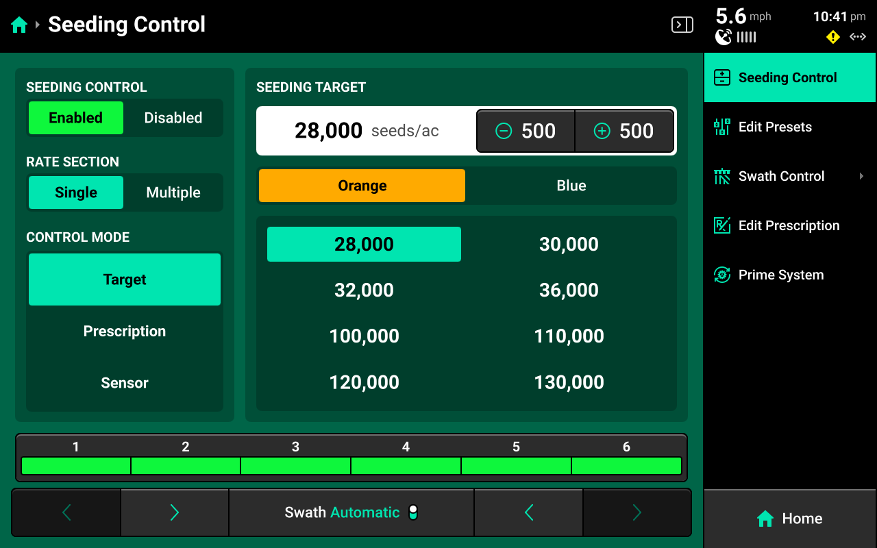
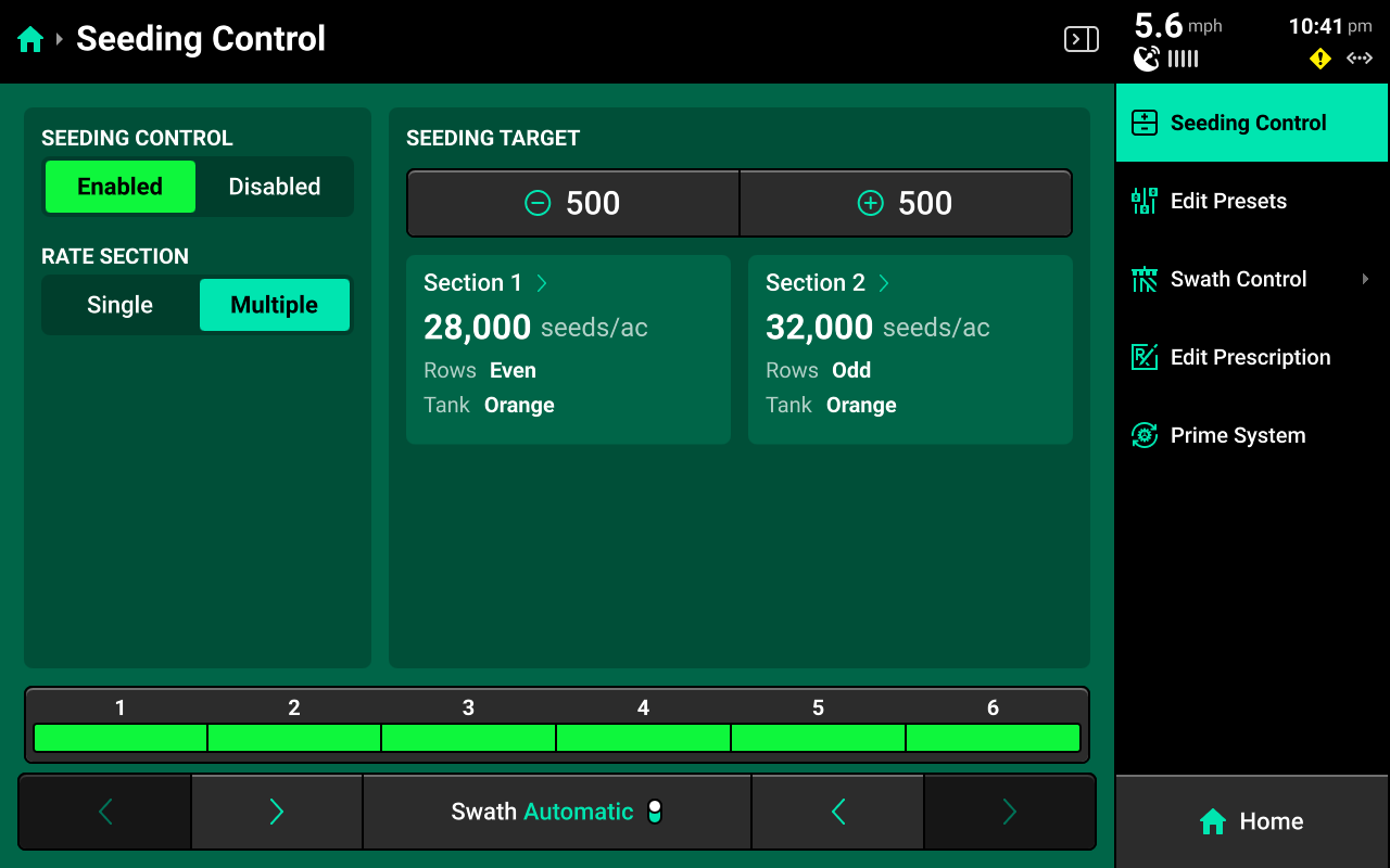
Press on any Control widget to open that system's Control Screen. Use the Control Screen to enable the system, select a rate for single / multiple rate sections, change from target (manual) rate to prescription or sensor control, edit prescriptions, access the Swath Control screen, or prime the system.
Orange Tank / Blue Tank options on all screens of 20|20 will only be available if a multi-hybrid seeding control product (mSet / vSet Select) is configured.
Target Control
Select Target under Control Mode to manually input a target rate for the system. The system will automatically adjust to hit the target based on inputs such as speed and row / nozzle spacing.
Single Rate Section
Enter a target rate for the entire system by pressing the white box under Seeding Target to enter a manual rate. Use the +(value) / -(value) buttons in the top center to adjust the rate by the indicated amount.
Presets
When using single rate section control, a table of presets is displayed in the center to allow the user to quickly switch between populations. Change these values by pressing Edit Presets on the right.
Multiple Rate Sections
Set Rate Section to multiple to set up multiple populations / rates for each rate section. Use the +(value) / -(value) buttons in the top center to adjust the rates for all sections by the indicated amount. Multiple rate sections must be configured in Systems to use this feature. See Other Systems in the Systems section of this guide for more details.
Prescription Control
Select Prescription under Control Mode to use a prescription file to control rate. A map of the prescription will be displayed in the center. Press Edit Prescription on the right to edit zone rates for the prescription.
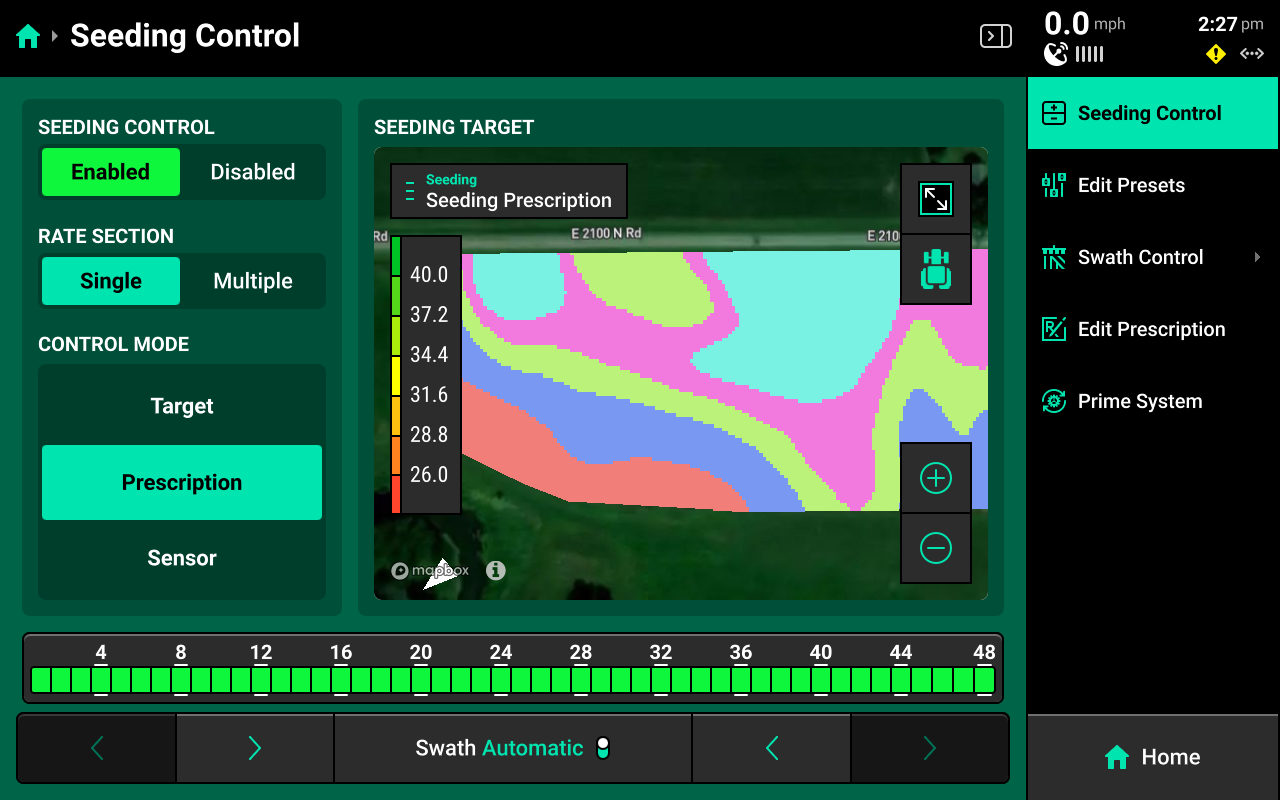
Prescriptions must be imported into the 20|20, and assigned to the active field before the user may enable prescription control. See Field Setup and Import Data to learn about importing and assigning prescriptions.
Edit Prescripiton Screen
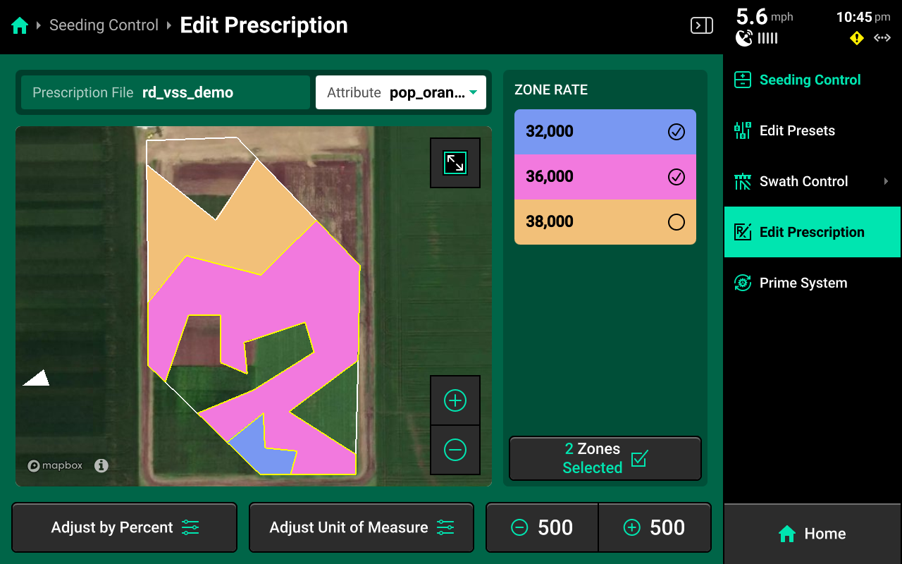
Select the desired attribute to edit using the dropdown box above the map, then select the desired zones rates and use the buttons at the bottom to adjust those rates by a percent or by a preset value. Press Adjust Unit of Measure to switch between Imperial and Metric measurements for the selected zones.
Sensor Control
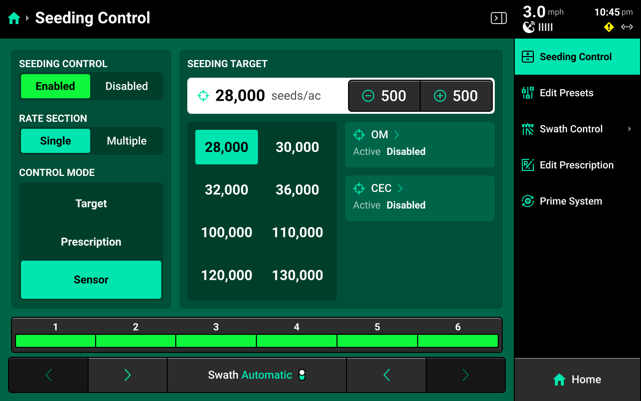
Some control systems may be configured to use a sensor to control rate. Sensors include SmartFirmers and Vision cameras. This guide details SmartFirmer sensor control setup. Refer to Vision documentation for information on setting up camera sensor control.
OM/CEC Control
Select Sensor under Control Mode and press OM or CEC in the center to configure either Organic Matter or Cation Exchange Capacity control parameters.
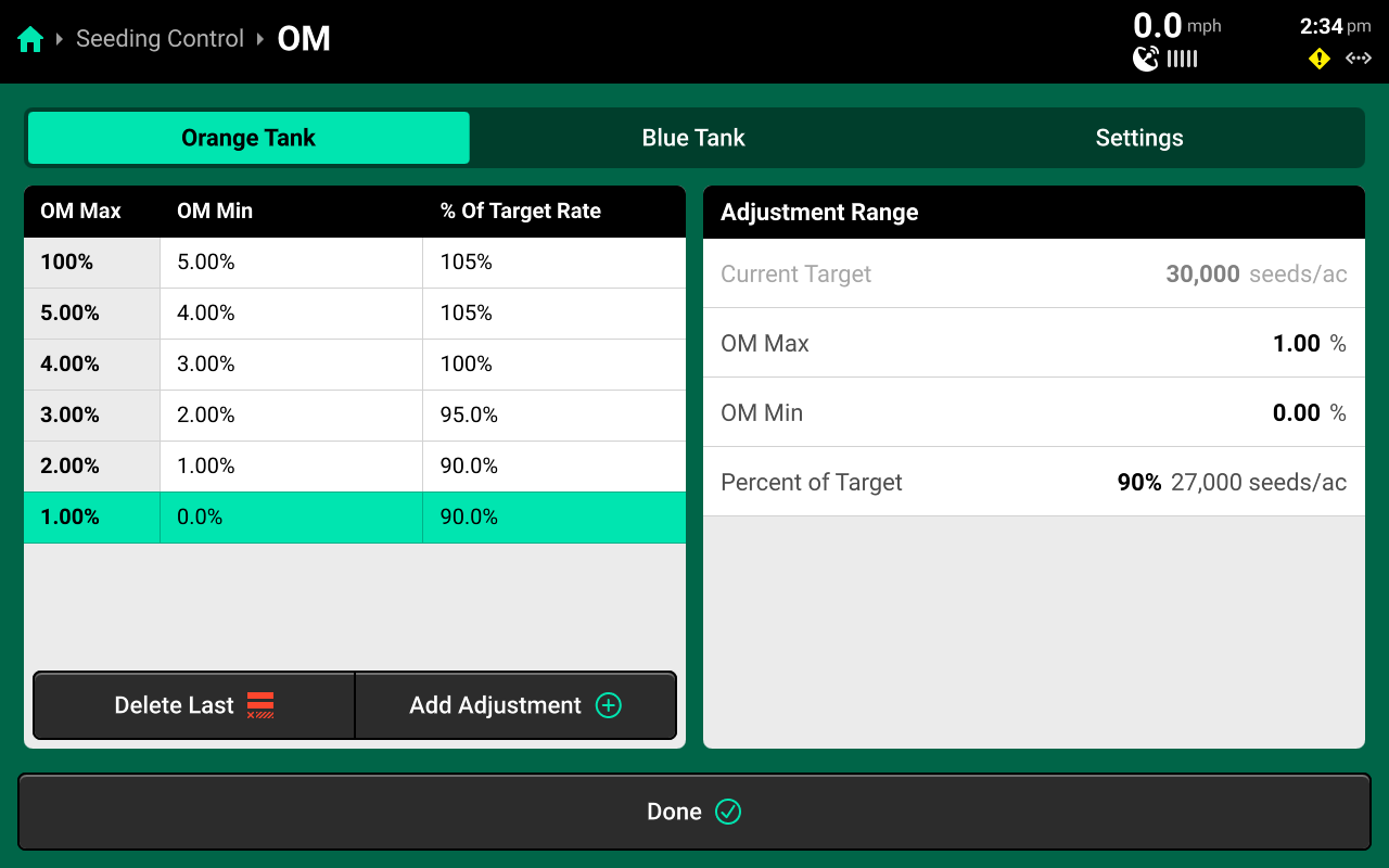
Select a Range in the left window, then use the settings in the right window to set values and desired rate for that range. To fine-tune control, press Add Adjustment + in the lower left window to add another range. Each range must be configured manually. Use the Settings tab at the top to toggle OM / CEC control between Enabled and Disabled.
It is required to add a max value of 100% to the first range, and a min value of 0% to the last range as "control layers" for the system. The max value of each range must be equal to the min value of the preceding range. See the above image for correct control layer setup.
Moisture Control
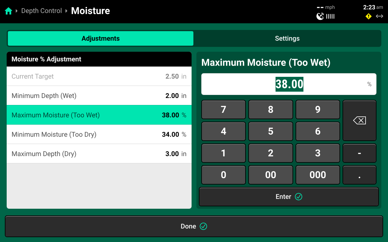
Use the right window to select moisture control parameters for SmartDepth and edit the selected values using the left window. Minimum Depth is the planting depth that the system will adjust towards when readings approach or exceed Maximum Moisture value. Maximum Depth is the planting depth that the system will adjust towards when readings approach or exceed the Minimum Moisture value. Use the Settings tab at the top to toggle Moisture Control between Enabled and Disabled. The system will control to the Current Target whenever sensor control is disabled.
Priming the System
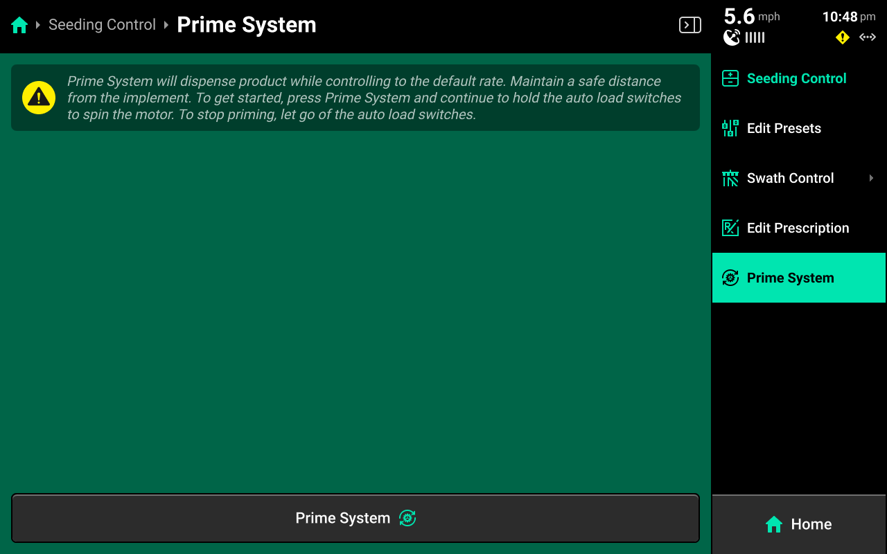
Press Prime System on the right to access the Prime System function. Press Prime System at the bottom of this screen to open a popup which instructs the user to hold both switches up to dispense product at the system's default rate. The system will dispense as long as the switches are held up.
Product will only be dispensed for the specific system through which the Prime System function was accessed.
Controlling a Second Display
Three Large control widgets are available which may be used to control map or layout features of another display that is connected to the same DBM. This feature may be useful when one display is mounted in a hard-to-reach area of the cab.
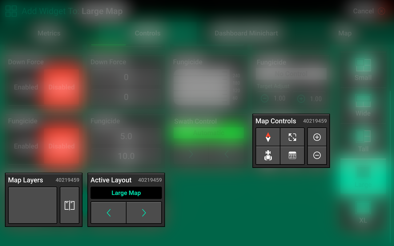
The number in the top right of each widget indicates the serial number of the display that the widget will control.
- Map Controls - Sets map zoom and orientation. See Controlling the Map for more details.
- Map Layers - Selects which map layer will display. See Controlling the Map for more details.
- Active Layout - Toggles between all saved layout tabs. See Home Screen Layout Tabs for more details.
Controlling the Map
The 20|20 displays high definition maps while operating. Different map layers may be selected and viewed during operation.
When connected to GPS, the map will default to displaying the tractor / implement in the center of the screen at a preset zoom level.
Control buttons are located on the map to adjust settings.
-
Press the Map Layer Name displayed in the top left to select a new map layer from the popup.
-
To split the map viewing area into two maps, press Split Icon
 in the top right of the map. When viewing two maps simultaneously, any adjustments done to one map (other than adjusting the legend) are also applied to the other map. (e.g. zooming in on one map will also zoom in on the other map.)
To exit the split map view, press the Full Icon
in the top right of the map. When viewing two maps simultaneously, any adjustments done to one map (other than adjusting the legend) are also applied to the other map. (e.g. zooming in on one map will also zoom in on the other map.)
To exit the split map view, press the Full Icon  on either map to change the view to only that map.
 -
The Compass Icon
 indicates north. Change the map orientation by pressing the compass. There are three orientation modes:
-
North Facing – The top of the map is always pointed north. The implement will change directions on the screen. This is the default orientation mode.
-
Implement Facing – The implement icon is always pointed towards the top of the screen and the map rotates around the implement.
-
Custom — place two fingers on the map and rotate it. This will lock the map into the selected orientation. Press the compass to return to north facing mode
-
-
Press the Field Icon
 to show the entire field.
 -
Press the Implement Icon
 or
or  or
or  to keep the implement centered in the screen. Zoom level will be reset.
 -
Press the Perspective Icon
 or
or  or
or  to toggle the map view angle between 0, 65, and 75 degrees.
 -
Press the Zoom Buttons

 to change zoom level. Alternatively, use a pinch-in or -out gesture with two fingers to change zoom level.
 -
Press the Legend Icon
 to show / hide the map legend. The map legend will display differently for each map layer. Most legends may be edited. Press and hold on the legend and drag up / down to adjust the high or low ends of the legend.
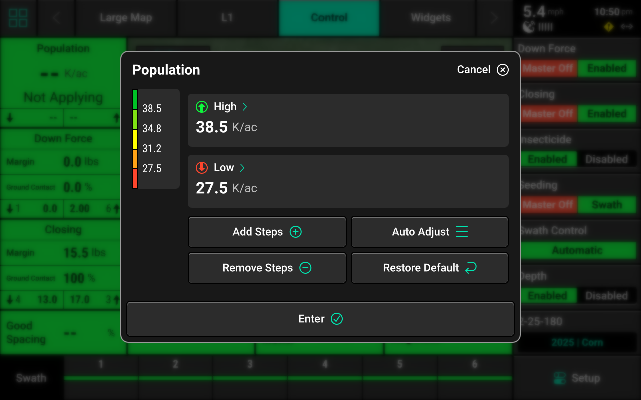
Tap on the legend to open a popup that allows for adjustment of high / low values and number of steps, or use the auto-adjust button to automatically add a set number of steps.
to show / hide the map legend. The map legend will display differently for each map layer. Most legends may be edited. Press and hold on the legend and drag up / down to adjust the high or low ends of the legend.
Tap on the legend to open a popup that allows for adjustment of high / low values and number of steps, or use the auto-adjust button to automatically add a set number of steps.
Press Enter to return to the home screen.
General Mapping Principles
- All maps are generated at 5Hz except for SRI (2Hz), meaning there are 5 data points mapped for each second of time.
- Mapping is drawn on a row-by-row basis.
- A dark line will be mapped on either side of the implement to distinguish passes.
- Rows which are inactive or are not collecting information on a row will not map (e.g. a row does not have load cell installed will not map down force).
- Active map layers may be changed at any time by selecting a different layer.
- Some map layers require specific Precision Planting products to be installed on the implement to generate the information necessary to create that layer.
- Some map layers will not be generated until application begins.
- If the map has moved away from the tractor / implement location, a white arrow will appear on the edge of the map pointing in the direction of the tractor / implement.
Swath Control Screen
The Swath Control screen allows the user to manually swath rows on / off, configure a swath control plan, record a boundary, or simulate headlands.
Swath Settings
Use these settings to determine how the 20|20 draws coverage, to change which parameters the 20|20 will use to swath on / off, or to enter an offset to use when recording boundaries.
The 20|20 will not swath off to any option under Swath Control Plan which is set to Disabled.
Setting Always Draw Coverage to Enabled will cause the 20|20 to draw coverage whether the implement is actively planting / spraying / etc. or not.
Simulated Headlands
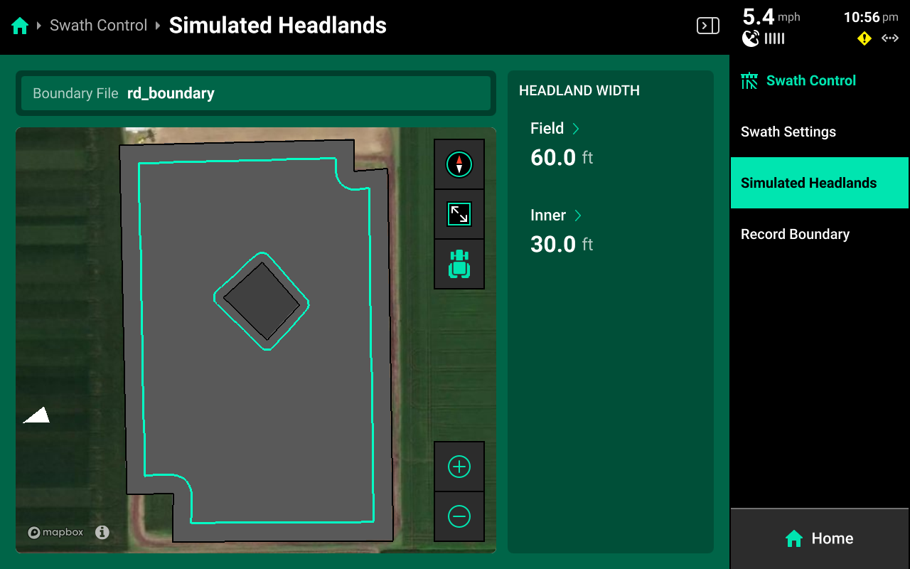
Select a width for Field (Exterior) or Inner to set the simulated headland width for either option.
A Boundary file must be assigned to the field to enable simulated headlands.
Recording Boundaries
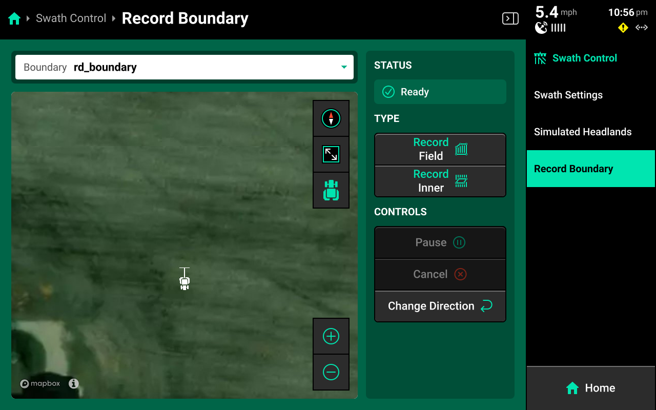
Use the following process to record a boundary using the 20|20.
- Use the dropdown menu to select an existing boundary to rewrite, or create a new file name.
- Press Record Field (Exterior) or Record Inner to begin recording either type of boundary.
- Use Pause or Cancel to temporarily or permanently stop recording the current boundary. Use Resume to unpause.
- Use Change Direction to correct the tractor heading, if necessary.
- Press Save to keep the current recording.
To ensure maximum accuracy around outer field corners, press Pause after reaching an outer corner. Complete the turn, then back fully into the corner. Press Resume when the tractor is properly repositioned.
Status Center
The Status Center is displayed in the top right of the Home Screen and contains at-a-glance information about Speed, GPS, Internet / Panorama connectivity, and system alerts.
Speed
The GPS Icon ![]() indicates that GPS is being used as the primary speed source.
indicates that GPS is being used as the primary speed source.
The Radar Icon ![]() indicates that Radar is being used as the primary speed source.
indicates that Radar is being used as the primary speed source.
The Wheel Icon ![]() indicates that a Wheel Speed Sensor is being used as the primary speed source.
indicates that a Wheel Speed Sensor is being used as the primary speed source.
The Reverse Icon ![]() indicates that the implement is moving in reverse.
indicates that the implement is moving in reverse.
Connections
The WiFi Icon ![]() indicates that the 20|20 is connected to a wireless network.
indicates that the 20|20 is connected to a wireless network.
The Ethernet Icon ![]() indicates that a hardwired internet connection is active.
indicates that a hardwired internet connection is active.
The Panorama Icon ![]() indicates that a connection to Panorama is active.
indicates that a connection to Panorama is active.
The Passmaster Icon ![]() indicates that data sharing between implements is active.
indicates that data sharing between implements is active.
Miscellaneous
The Battery Icon ![]() indicates that a fault is detected with the internal battery of the DBM. In the case of a power source disconnect, data may not be saved.
indicates that a fault is detected with the internal battery of the DBM. In the case of a power source disconnect, data may not be saved.
The Master On / Off Icon ![]() /
/ ![]() indicates the position of the Master Switch.
indicates the position of the Master Switch.
The Caution Icon ![]() indicates an active diagnostic event.
indicates an active diagnostic event.
Details
Press the Status Center to open a popup with more detailed information.
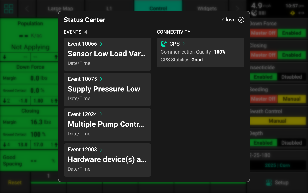
Press any of the events to open a detailed description of that event. Press GPS to navigate to the GPS section of the Diagnose screen. See GPS for more details.
Screenshots
To take a screenshot, press and hold in the upper right corner of the screen until the screen flashes white. This action may be performed at any time and in any menu of the 20|20. See Export Data for information on exporting screenshots to a USB drive.
 Setup
Setup
Press Setup to open the Navigation Menu. The Navigation Menu displays a screen with basic implement information and allows the user to navigate to the different sub-menus of the 20|20. The system pathway displayed in the top right will help the user to orient themselves while navigating the 20|20.
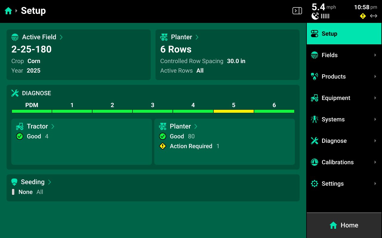
Navigation Menu Overview
-
Fields: Change the active field, assign prescriptions/boundaries, create or edit Client, Farm, & Fields, change crop, and share data using Passmaster.
-
Products: Set up / assign crop hybrids and tank mixes.
-
Equipment: Configure the implement and tractor measurements, set up Ethernet devices and CAN buses, view / change GPS, Radar, and Quick Start settings, and save or load Equipment profiles.
-
Systems: Configure all Precision Planting products installed on the implement.
-
Diagnose: Access diagnostic information related to the display and all products being controlled / monitored on the implement.
-
Calibrations: Run all calibrations for the implement, tractor and other systems.
-
Settings: Import / export / delete data, perform software updates, connect to the Internet / Panorama, and change user preferences associated with the monitor.
Alerts are accessible for each system on the specific system screen. See Alerts for more details
Using the Navigation Menu
Nested Menus
2025.1.x software utilizes a nested navigation theme. Press on any of the sub-menus displayed in the Navigation Menu to jump to the Landing Screen for that sub-menu. The sub-menu will then expand in the Navigation Menu, displaying additional sub-menus for the previous selection. Instead of using a Back button, instead press any option in the Navigation Menu to return to that page.
Several sub-menus allow the user to add different types of hardware to an Equipment profile or System. Whenever a hardware device is added, that hardware will appear in the Navigation Menu under the Equipment or System that it was added to.
Press on the desired hardware device in the Navigation Menu to quickly access Install Settings for that device. See Hardware Setup for more information on Install Settings and Operation Settings.
Navigation Icons
Several types of icons exist which indicate actions that may be performed by the user as they navigate the different screens of the 20|20
Three vertical dots ![]() may be pressed to access a Secondary Menu for the item on which they appear. The Secondary Menu allows the user to perform certain actions, such as updating / loading an Equipment profile or deleting a misconfigured hardware device.
may be pressed to access a Secondary Menu for the item on which they appear. The Secondary Menu allows the user to perform certain actions, such as updating / loading an Equipment profile or deleting a misconfigured hardware device.
Arrows ![]() , indicate that an item may be pressed to navigate to a different screen, rather than using the Navigation Menu.
, indicate that an item may be pressed to navigate to a different screen, rather than using the Navigation Menu.
![]()
Expanding Screen
Press the ![]() button in the top right to collapse the Navigation Menu to provide additional viewing space in the center screen. Press the
button in the top right to collapse the Navigation Menu to provide additional viewing space in the center screen. Press the ![]() Icon when the menu is hidden to show it again.
Icon when the menu is hidden to show it again.
Navigating the 20|20
In the different screens of the 20|20, there will often be a right and left window displayed in the center screen. The left window is typically used to view and select various settings, while the right window is typically used to make changes to the selected setting.
When making changes to a setting using the left window, preset selections (e.g. toggling a setting between Enabled / Disabled) are automatically saved once pressed. When using a keypad to input values (e.g. editing preset population / rate values), it is necessary to press Enter to save the new value.
Crop Settings
Different settings in the menus of the 20|20 are designated as Crop Settings, indicated by the Crop Setting icon ![]() .
.
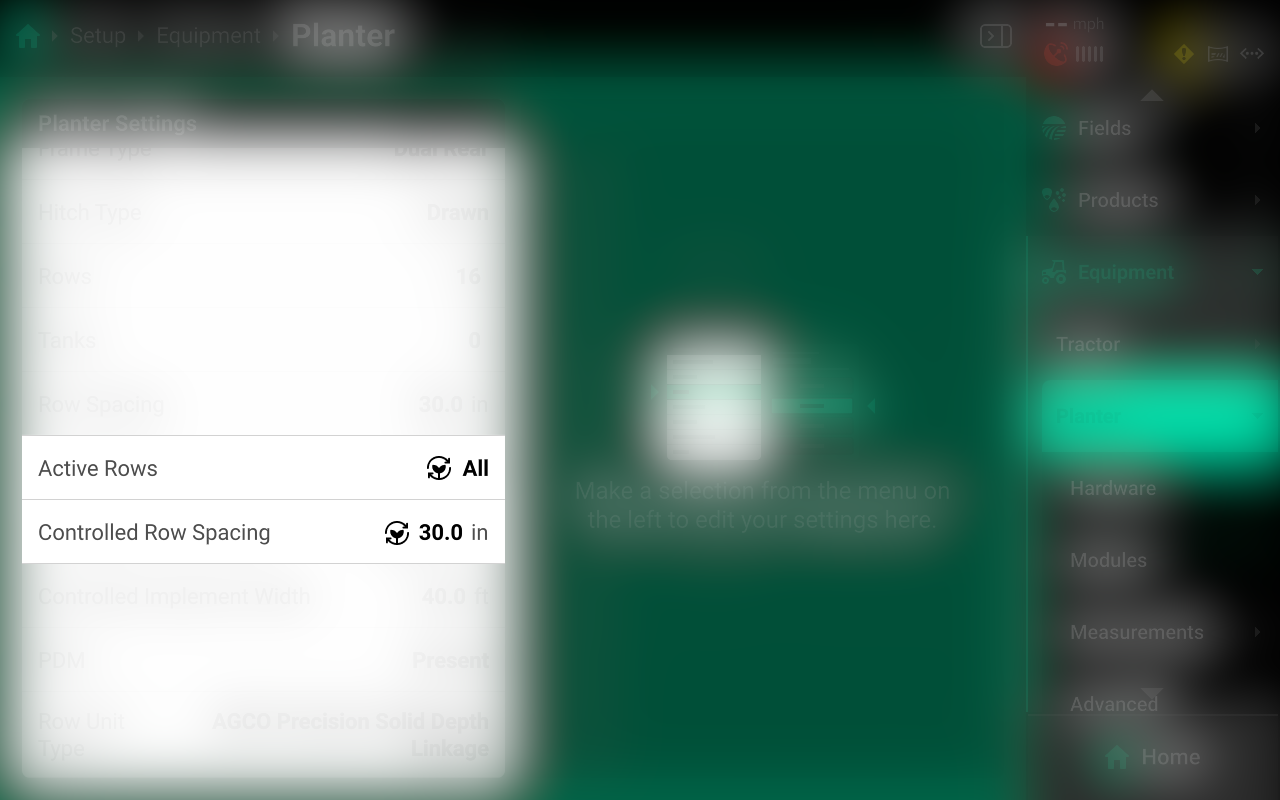
All Crop Setting changes will be saved to the current active crop. After switching from a new crop back to any other previous crop, all Crop Settings will revert to the last saved value for that crop. Use this feature to streamline the process of changing from one crop to another.
For example, a user may switch the Active Crop from Corn to Soybeans, and then select the correct Seeds / Disk setting and the correct Active Rows setting for Soybeans. When the user switches the Active Crop back to Corn, the 20|20 will automatically revert those settings back to the last active values for Corn. When the user switches the Active Crop back to Soybeans, the 20|20 will revert those settings again.
All Crop Settings have the same default values. The user must change each of the desired values once with the correct crop active to save those settings to the desired crop.
List of Crop Settings
The following list indicates which settings are saved to the Active Crop.
-
Setup > Equipment
- Active Rows
- Controlled Row Spacing
-
Setup > Systems
- Default Population / Rate
- Seeds per Disk
 Fields
The Fields menu is used to:
- Create and edit Clients, Farms, and Fields
- Set the active crop for each field.
- Select the season start year.
- Assign imported boundaries and prescriptions.
- Change the Active Pass to replant or make multiple sprayer passes.
- Change some critical Operation Settings, such as seeds / disk.
- Share data with other 20|20 monitors using Passmaster.
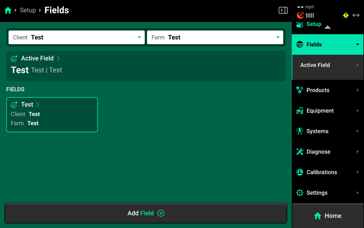
Precision Planting uses a three-tiered naming structure for field names: Client > Farm > Field. Each tier of the naming structure becomes more specific. A table of all fields is displayed on the Fields Landing Screen. This table may be filtered by Client and Farm using the dropdown boxes at the top. At all times there will be an active field, designated by a blue-green outline. The active field is the field in which all data and mapping is currently being created for and stored under.
Press Add New Client / Farm from either of the dropdown boxes to add a new Client or Farm.
Press Add Field + at the bottom to add a new field to the selected Client / Farm.
Press the ![]() Icon next to any field name to delete Client, Farm, or Field.
Icon next to any field name to delete Client, Farm, or Field.
The active Client / Farm / Field cannot be deleted.
To delete a misspelled Client or Farm, a Farm and / or Field must be created under the misspelled entry for the delete option to be available.
Pressing on any field in the table will jump to the Field Setup screen.
Field Setup
Use the tabs at the top to navigate to the different areas of Field Setup.
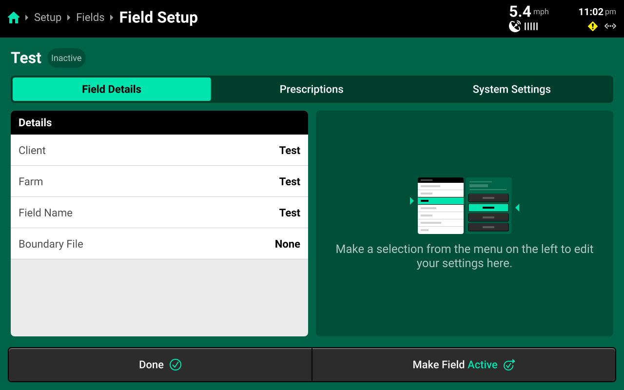
Field Details
Use this tab to:
- Make a field active using the button at the bottom. If the field is already active, this button will read Field Activated. Press Done instead to exit field setup without making the field active.
- Change the Client / Farm that the field is assigned to.
- Change field name.
- Assign a boundary file.
Boundary assignments are saved to the Equipment profile per Year. When switching Implement types (e.g. from planter to sprayer) or changing the Year, it will be necessary to reassign boundaries on field setup.
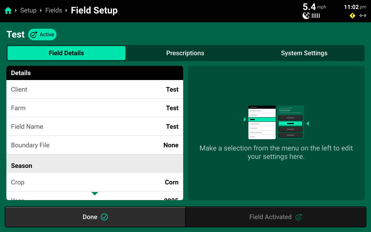
- Change field Crop setting (Active Field only).
- Change crop year setting (Active Field only).
- Change the active pass to ignore existing coverage when replanting or making multiple sprayer passes (Active Field only).
Prescriptions
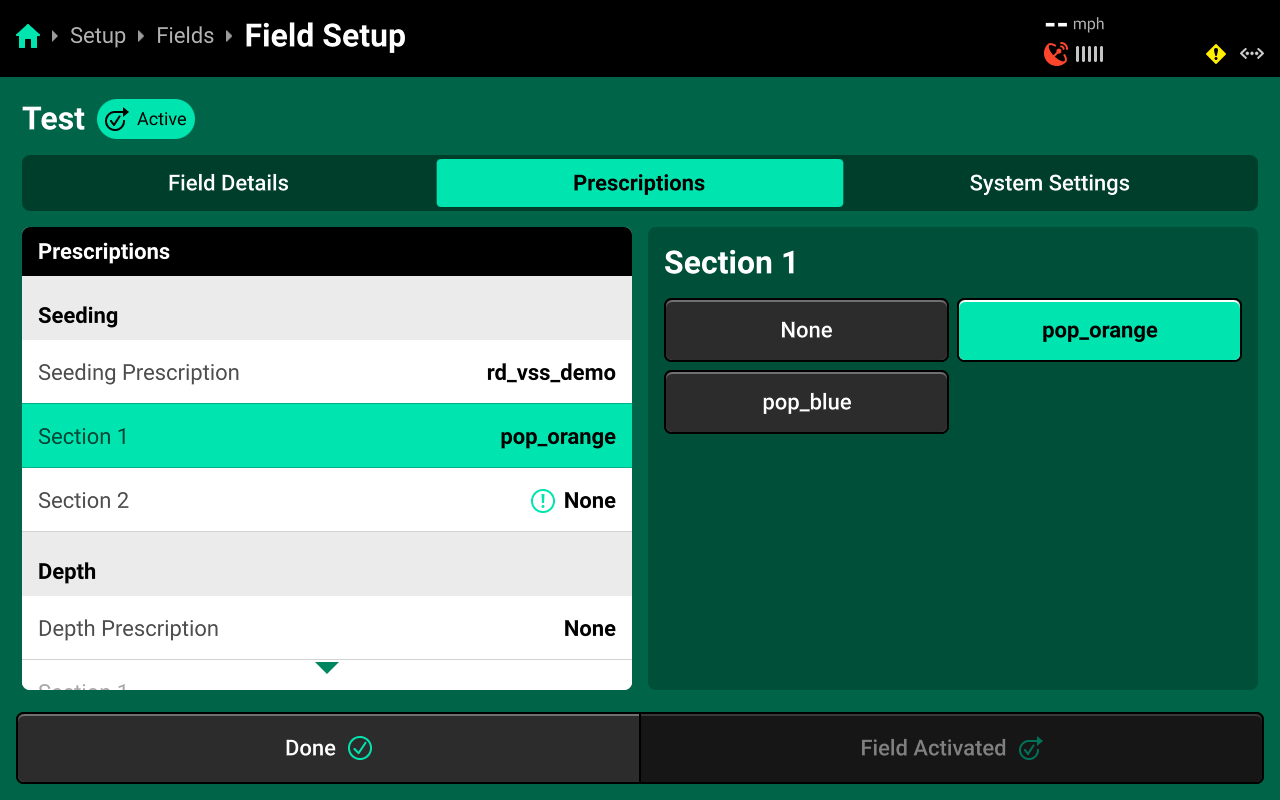
Use this tab to select and assign the desired prescription file and to assign an attribute of that file to the desired control (or rate) section. See the above image for a depiction of correctly assigning a prescription attribute to a control section.
Different systems, e.g. Granular, Seeding, etc. will appear in this window only after those systems have been configured.
Prescription assignments are saved to the Equipment profile per Year. When either is changed, it will be necessary to reassign prescriptions.
Prescriptions are not imported into the display on this screen. Navigate to Setup > Systems > Import to import all types of data into the 20|20.
The Edit Prescription screen is not available from the fields screen. To access the Edit Prescription screen, open the appropriate Control Screen once a prescription has been assigned and select Edit Prescription on the right. See Control Screens for more details.
System Settings
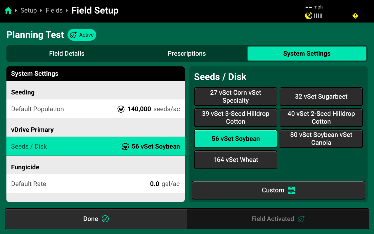
Use this tab to change Operation Settings for different system hardware devices, such as seeds/disk. Changes made here will apply to all applicable hardware devices in the selected system across all rows.
Active Field
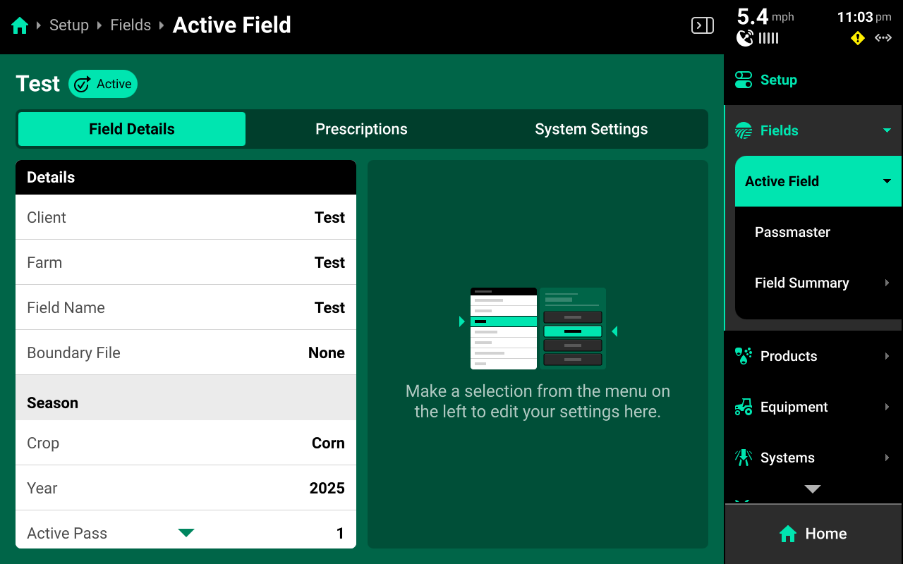
Press the active field on the Fields Landing Screen, or press Active Field under Fields in the Navigation Menu to navigate to the Active Field screen. Use this screen to access all options from the Field Setup screen with the Navigation Menu still visible.
Passmaster
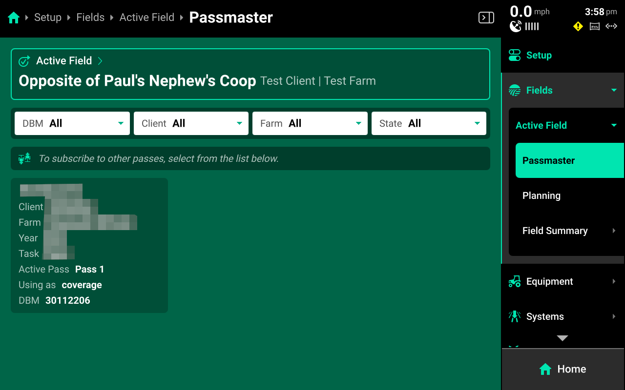
Press Passmaster under Active Field in the Navigation Menu to share field maps between multiple 20|20 monitors that are paired with the same Panorama operation. This is referred to as "Subscribing" to a pass. Data sharing is not limited to Coverage - all data will be shared. Data sharing is field-specific, the user must select what passes to subscribe to for each Active Field on each DBM.
A table of all field map data sets, or passes, are displayed on this screen. Press any pass to begin subscribing to it. Any pass that is subscribed to is indicated by a blue-green outline. Press the ![]() Icon on a subscribed pass and press Disconnect to stop subscribing to it.
Icon on a subscribed pass and press Disconnect to stop subscribing to it.
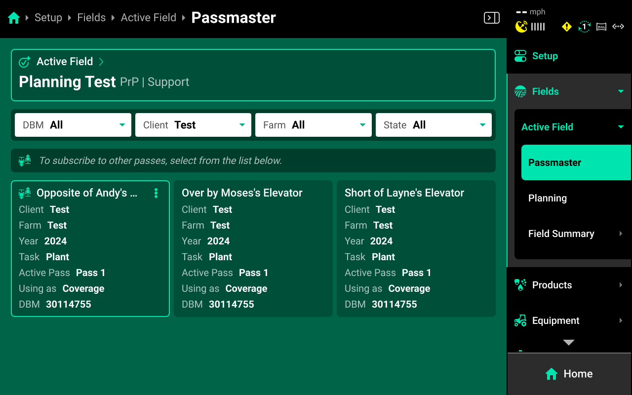
This table may be filtered by DBM Name, Client, Farm or State using the filters at the top. The State filter is set to Active by default, which means that the table will only display passes which are actively generating data. To view all passes stored on the connected Panorama Operation, set this filter to All. This feature may be utilized to "download" previous swath coverage to the 20|20.
DBM Name for each pass will default to the serial number of the DBM which generated the pass. This name may be changed by accessing the DBM on Panorama.ag and changing the nickname.
Pass subscription is not limited by field name or Implement type. Any pass / number of passes may be subscribed to. However, map layers on the home screen will only build for systems that are installed and configured on each implement / 20|20. Coverage will always build.
The speed of data sharing will be limited by Internet connection quality for all sharing 20|20 monitors. With high-quality Internet connections, data sharing can appear to be live. Lower quality connections will have increased delay. Precision Planting recommends 1mb upload / 1mb download speed per sharing DBM.
The Passmaster feature is data-intensive. Smart phone and tablet hotspots are designed for short-term download usage and do not have the long-term connectivity and upload speed capabilities necessary for Passmaster data sharing. Precision Planting Product Support strongly recommends using a third-party dedicated router for any live Passmaster data sharing.
Troubleshooting for smart phone and tablet hotspot connection issues will be limited to restarting and reconnecting to the hotspot.
Planning
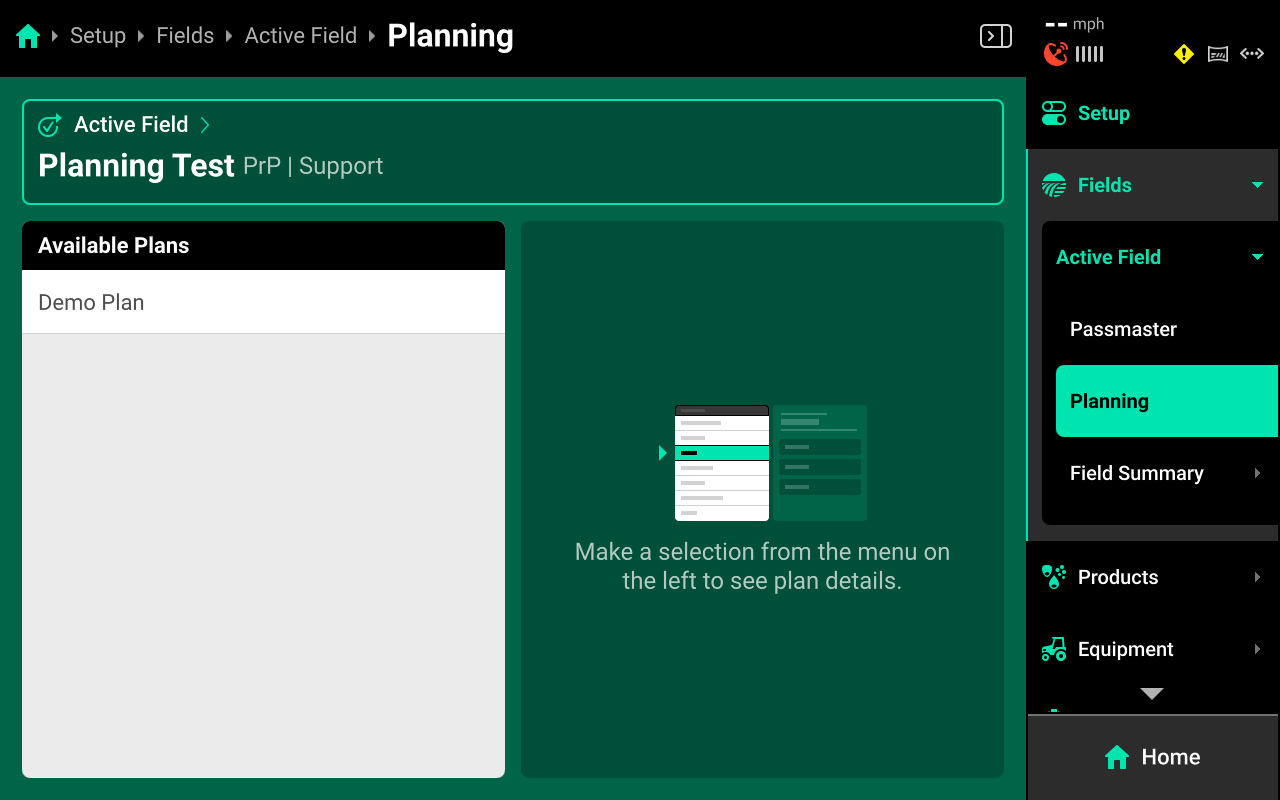
Use this screen to download field (work) plans from a connected Panorama operation. See the Panorama Planning Guide for more information on creating plans in Panorama.
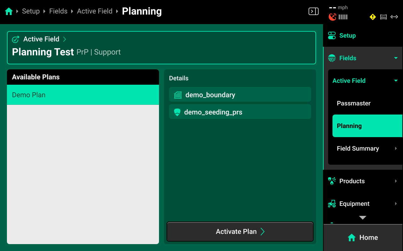
Any plan which has been created in Panorama for the current Active Field will be displayed in the left window. Press any plan to view plan details in the right window. Press Activate Plan in the lower right to open the plan activation wizard.
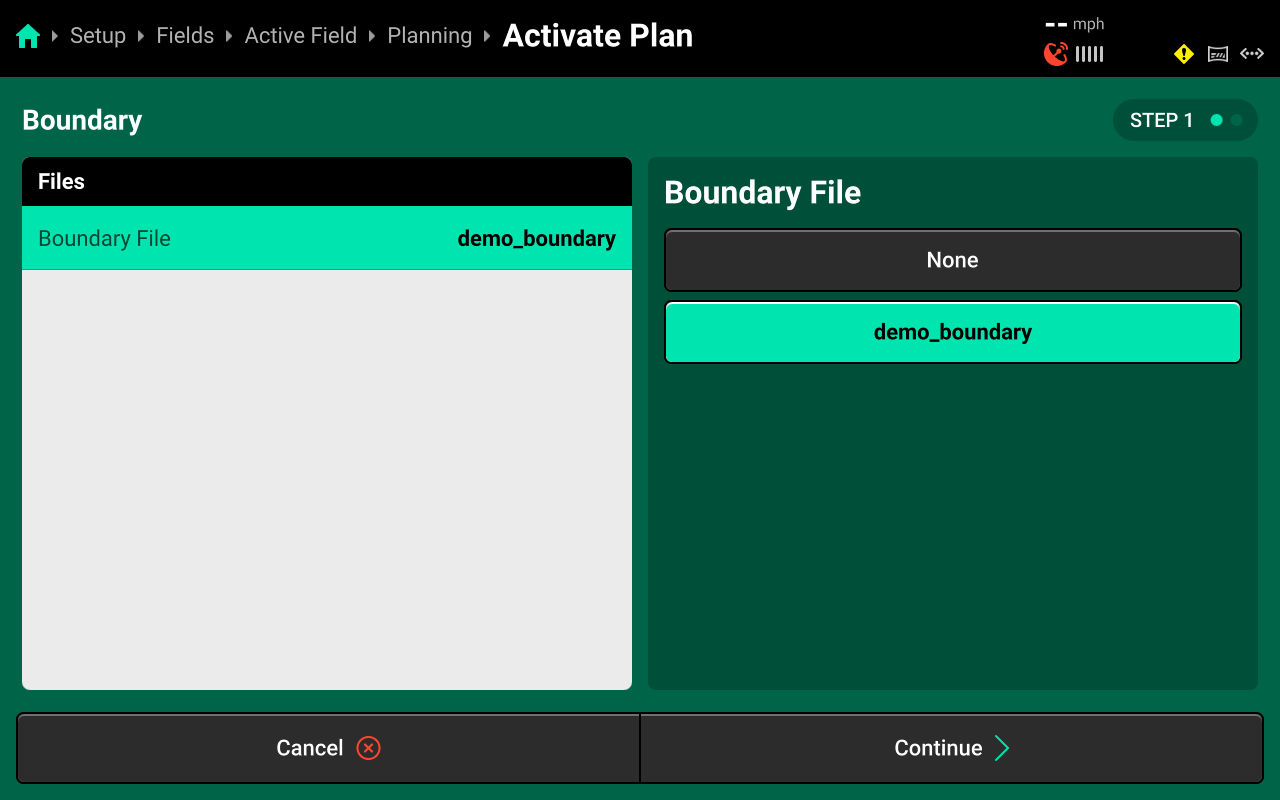
Use Step 1 to view or change the assigned boundary file. Press on the plan boundary to change it with any boundary that is saved to the plan using the list in the right window.
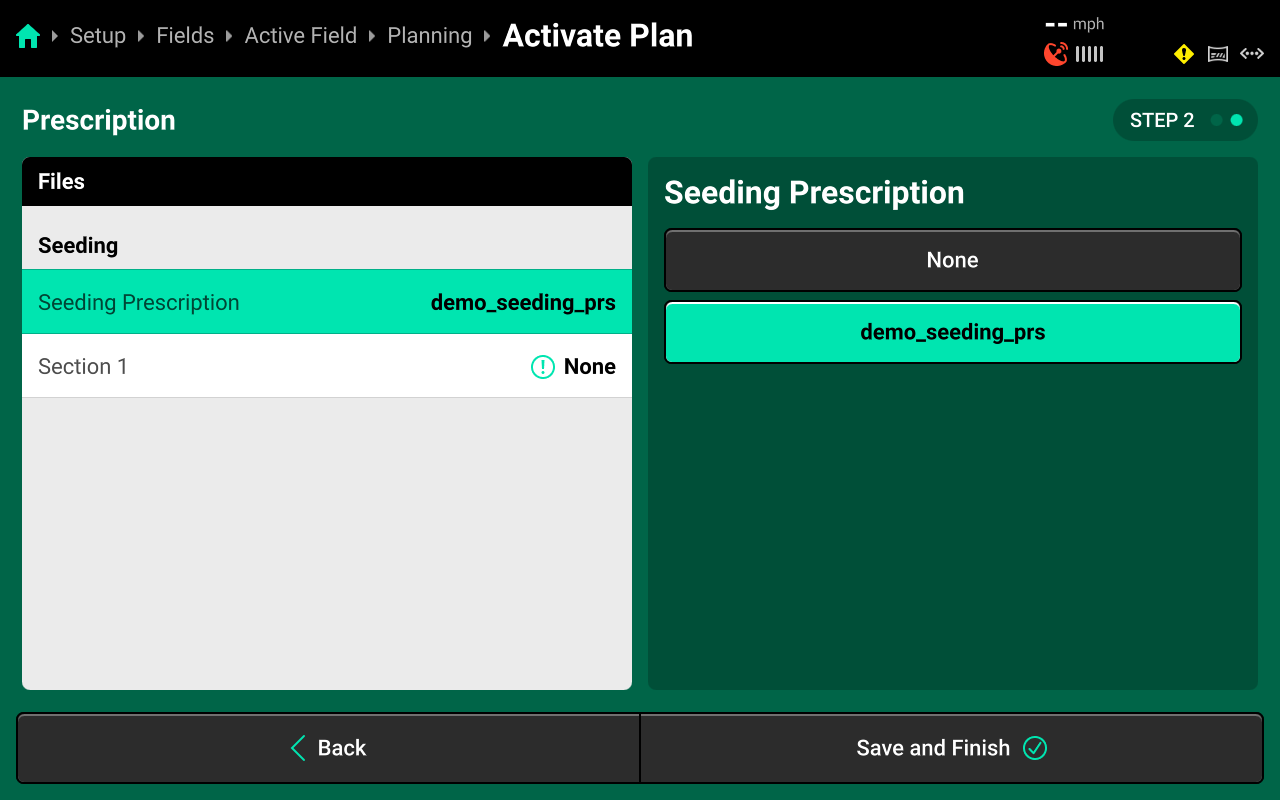
Use Step 2 to view or change the assigned prescription file for each system and to assign a prescription attribute to the correct rate sections(s). Press on the plan prescription to change it with any prescription that is saved to the plan using the list in the right window.
Press on the desired rate section(s) under each system to manually assign a prescription attribute to that rate section using list in the right window.
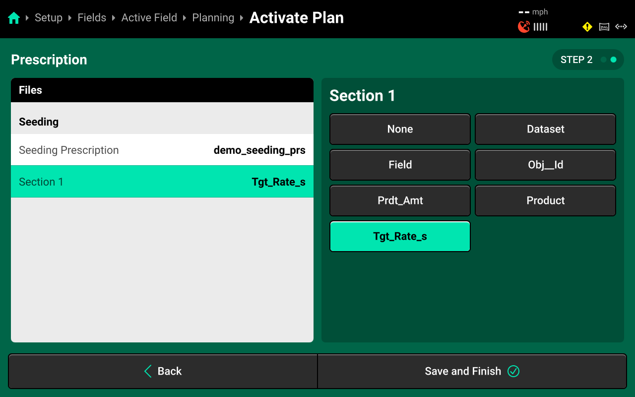
Prescription control will not be enabled unless each used rate section has an attribute manually assigned to it.
Press Save and Finish to exit the wizard.
Field Summary
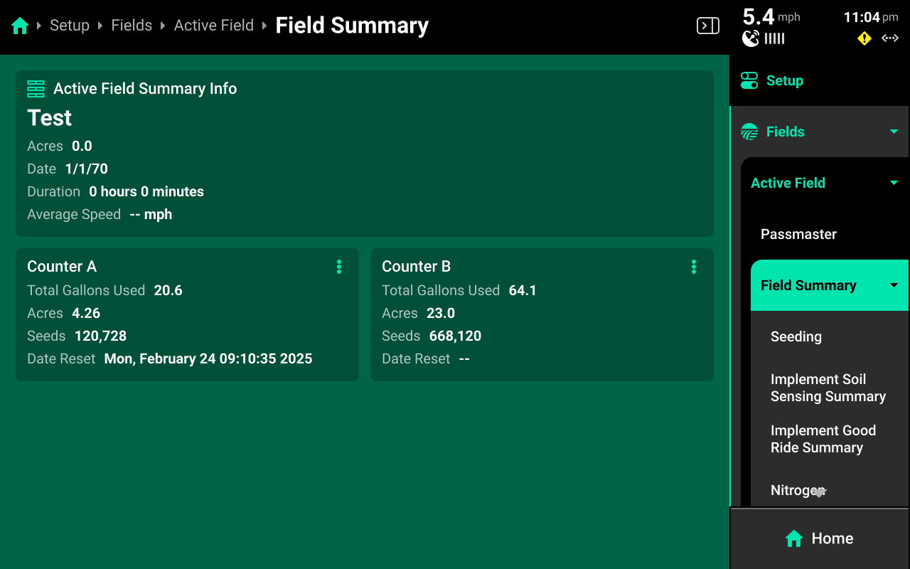
Use this screen to view various field-related metrics for the active field. General information, such as hours, acre counters and seed count is shown after navigating to Field Summary.
Press any of the options under Field Summary the Navigation Menu to view detailed information regarding hybrids, tank mixes, or systems. Use the tabs at the top to switch between the current pass summary and the entire field summary.
"Pass" in this context refers to the current field coverage map and its map layers, not a single down-and-back pass.
Press the ![]() Icon on each counter to reset it.
Icon on each counter to reset it.
 Products
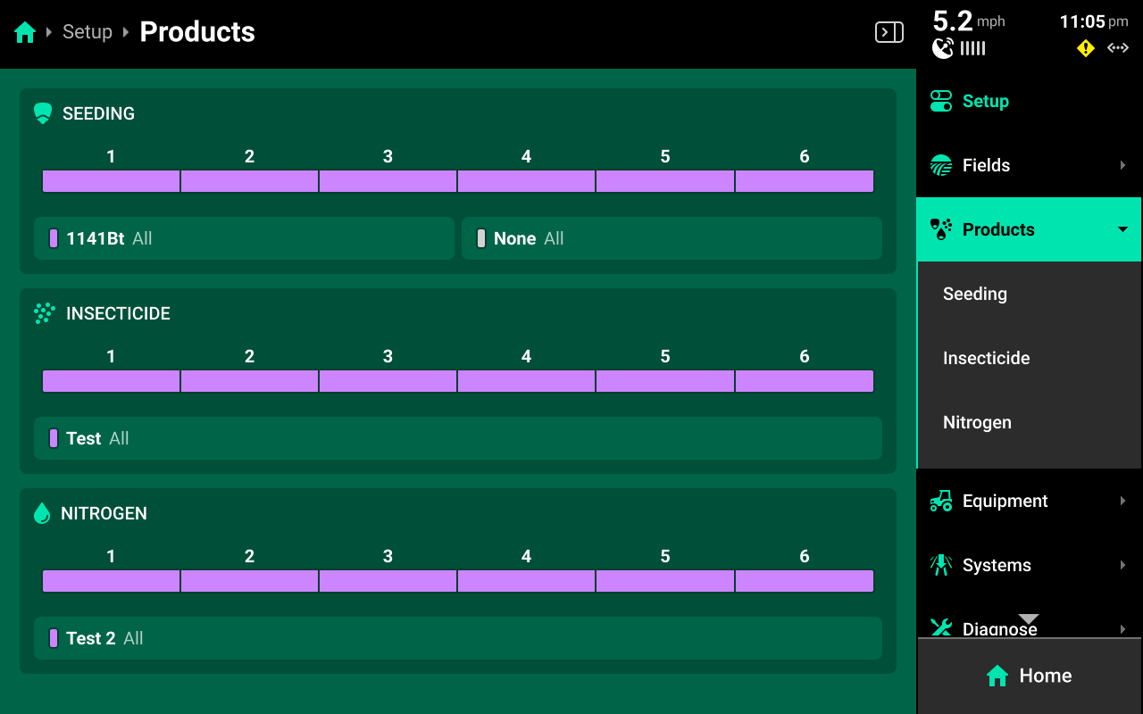
The Products menu is used to set up all hybrids and granular / liquid tank mixes. A list of seeding, liquid, and granular systems showing basic hybrid / tank mix information and indicating active rows for the hybrid / tank mix is shown on the Products Landing Screen.
Systems will not appear on this screen for hybrid / tank mix setup until that system is configured under Setup > Systems.
Hybrids
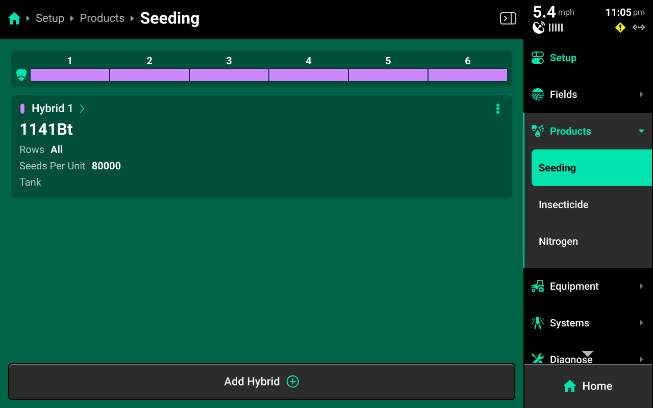
Press [Seeding System Name] under Products to add, delete or modify hybrids. A table of hybrid entries is displayed in the center. Press Add Hybrid + to immediately add a numbered hybrid entry to this table. Press the ![]() Icon next to any entry displayed in the table to delete it.
Icon next to any entry displayed in the table to delete it.
Press on any entry once it has been added to open Hybrid Setup.
Hybrid Setup
Use the Hybrid Setup screen to set the active rows for the hybrid, select or enter a hybrid name, modify hybrid volumetric attributes, or add a seed treatment.
The Hybrid Name list is limited to 10 names. Adding an eleventh name will remove the oldest name.
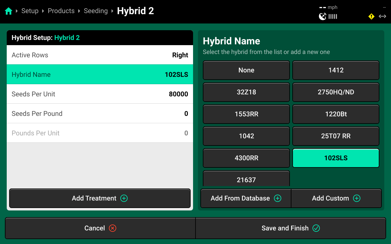
Precision Planting Product Support recommends using the table of hybrid entries displayed on Setup > Products > [Seeding System Name] as the "master list" of hybrids, rather than the Hybrid Name list on the Hybrid Setup screen. Select a hybrid entry and modify the active rows to "change" hybrids. Adding / deleting hybrids from the list on the Hybrid Setup screen will not remove saved names for the entries. The list of hybrid entries is saved to the Equipment profile.
Tank Mixes
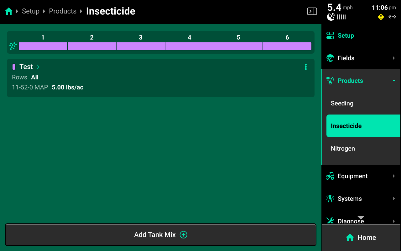
Press any of the liquid or granular systems under Products to add, delete, or modify tank mixes. A table of all tank mixes for the selected system is displayed in the center. Press Add Tank Mix + and enter the desired name for the tank mix. A new tank mix will then be displayed in the table.
Press on any tank mix in the table to set active rows for that mix and add granular or liquid products to it. Press the ![]() Icon next to any enrty displayed in the table to delete it.
Icon next to any enrty displayed in the table to delete it.
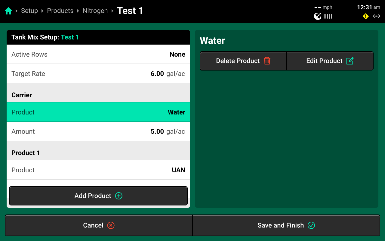
If setting up a liquid tank mix with a carrier, the carrier must be added first. Changing Target Rate on this screen will increase only the amount of carrier. See the above image for an example. The system will continue to apply the rate commended in the Control Screen, regardless of tank mix ratio.
The 20|20 will not indicate on the map when a new product is added to an existing tank mix. To track changes to a mix on the map, set up a new mix instead of editing an existing mix.
 Equipment
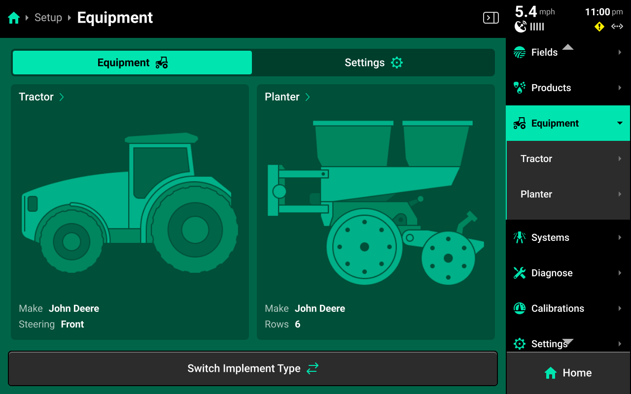
The Equipment menu is used to configure, save, and load different Cab or Implement profiles. Use this menu to enter all Cab / Implement specifications and measurements, to configure GPS and Radar location and settings, and to set up Ethernet / CAN.
Press Switch Implement Type at the bottom to select the desired Cab / Cart / Implement combination.
Switching Implement will erase any unsaved changes to the active Cab / Implement profiles. Ensure to save all changes before switching Implement.
A new 20|20 will display only a tractor cab on the Equipment Landing Page on first boot up. Press Switch Implement to select and configure the desired equipment combination. This will also occur if the user performs a Delete All Data.
Quick Start Settings
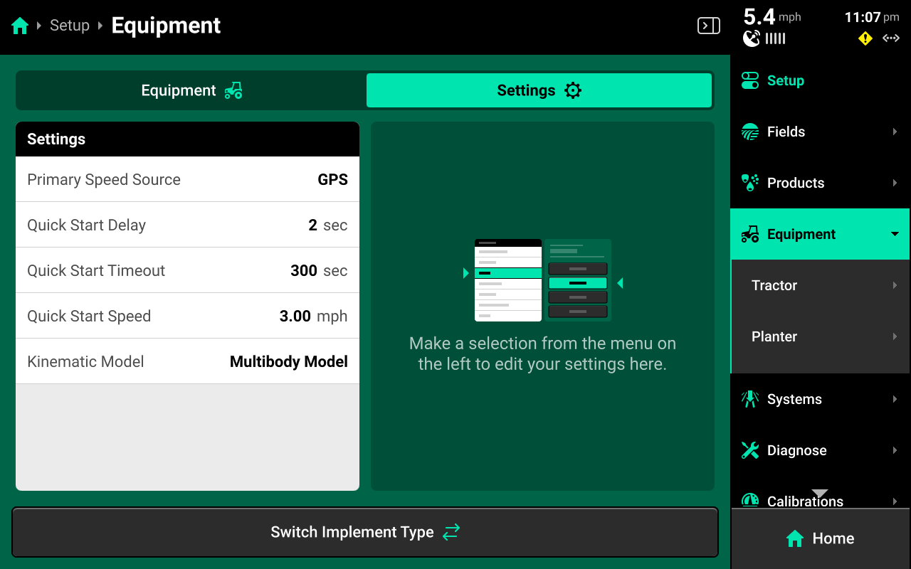
Use the tab at the top of the Equipment Landing Screen to select Settings for the Quick Start function. The Quick Start Control Widget will use the values from this screen when it is enabled. Quick Start allows the user to begin applying product at the simulated Quick Start Speed after the Quick Start Delay countdown. It will continue to run until either the Quick Start Timeout is reached, or until the 20|20 registers speed from the Primary Speed Source.
Kinematic Model and Primary Speed Source are not typically changed from their default settings (Multibody and GPS). Change these settings only when advised by Precision Planting Product Support.
Cab / Implement Setup
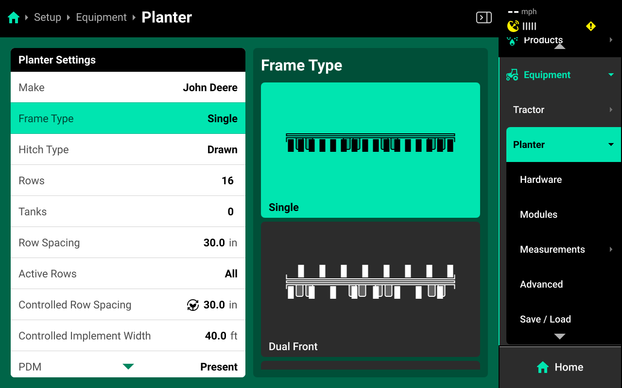
Select the Cab or Implement under the Equipment tab to begin setup.
Use the left window to select the desired parameter and the right to window to make changes to that parameter.
Select Advanced for Frame / Boom Type if utilizing the Advanced table to adjust individual row / nozzle positions. See Advanced for more details.
Row Spacing / Nozzle Spacing refers to the physical spacing between rows on the Implement. Controlled Spacing refers to the spacing between each of the current Active Rows. The 20|20 will use Controlled Row Spacing to determine population / rate.
It is not necessary to assign a value to Tanks unless a SRM for a Rate Control Module will be installed on the physical tank.
Ensure to set PDM to Not Present for systems using the single or triple CAN sensing harness. Also ensure to select the correct Row Unit when applicable.
Hardware
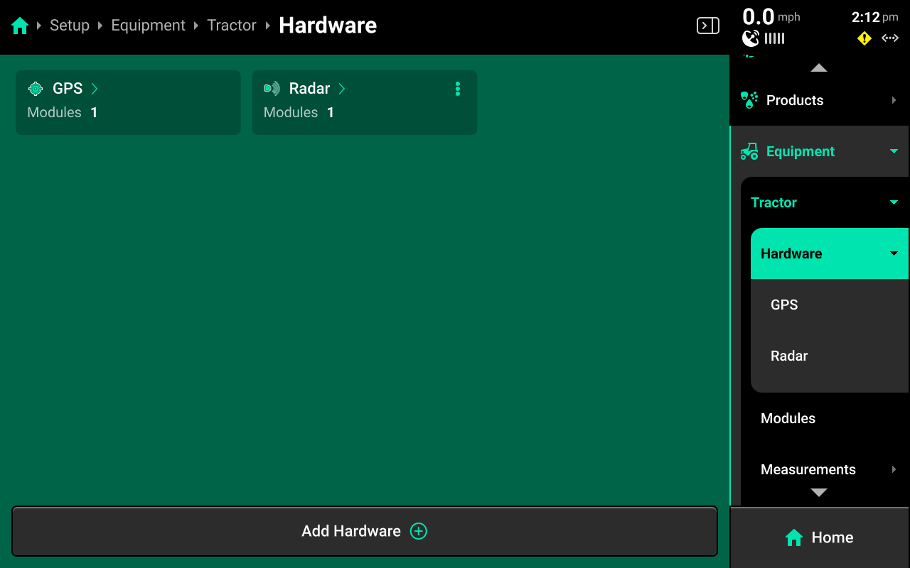
Use the Hardware screen to configure GPS receiver or Radar location by pressing Add Hardware + at the bottom and following the setup wizard. Press the ![]() Icon on any hardware device in the center of the Hardware screen to run the setup wizard again with Edit Locations or to delete it.
Icon on any hardware device in the center of the Hardware screen to run the setup wizard again with Edit Locations or to delete it.
All settings from the final step of the wizard may be accessed again by selecting the desired device under Hardware in the Navigation Menu.
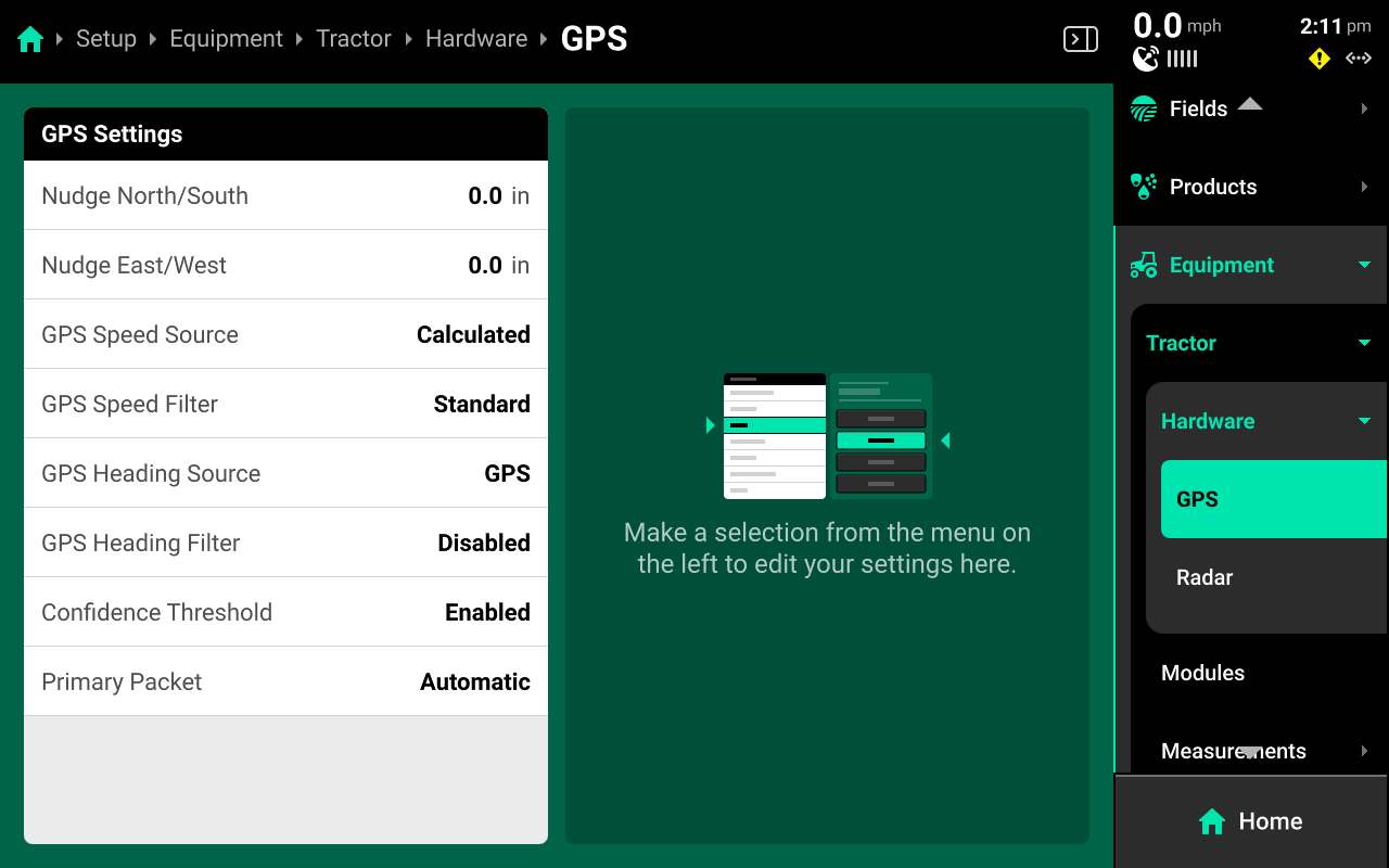
- Nudge North / South : Use this setting when experiencing GPS drift with lower accuracy GPS receivers to nudge GPS North or South by the input amount.
- Nudge East / West : Use this setting when experiencing GPS drift with lower accuracy GPS receivers to nudge GPS East or West by the input amount.
- GPS Speed Source : Change to use speed from the GPS receiver instead of allowing the 20|20 to calculate speed.
- GPS Speed Filter : Change the rate at which the 20|20 filters input data from the GPS receiver to help transistion smoothly between speed changes.
- GPS Heading Source : Change to use the heading reported by the GPS receiver instead of allowing the 20|20 to calculate heading.
- GPS Heading Filter : Change the rate at which the 20|20 filters input data from the GPS receiver to help transistion smoothly between heading changes.
- Confidence Threshold : Change whether the 20|20 will filter out irregularities in data from the GPS receiver.
- Primary Packet : Changes what protocol the 20|20 will use to determine the primary NMEA strings.
- Automatic : The 20|20 will automatically determine the best option.
- RMC : The 20|20 will always use RMC strings for the primary packet.
GPS location will default to the Cab. Adding GPS to the Implement hardware screen will remove it from the tractor, and vice versa. Configure GPS on the Implement only if the 20|20 is connected to a GPS receiver that is mounted on the Implement. Radar may not be added to the Implement.
Modules
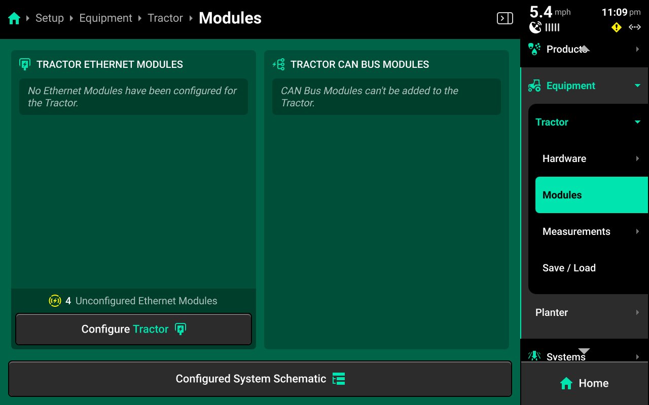
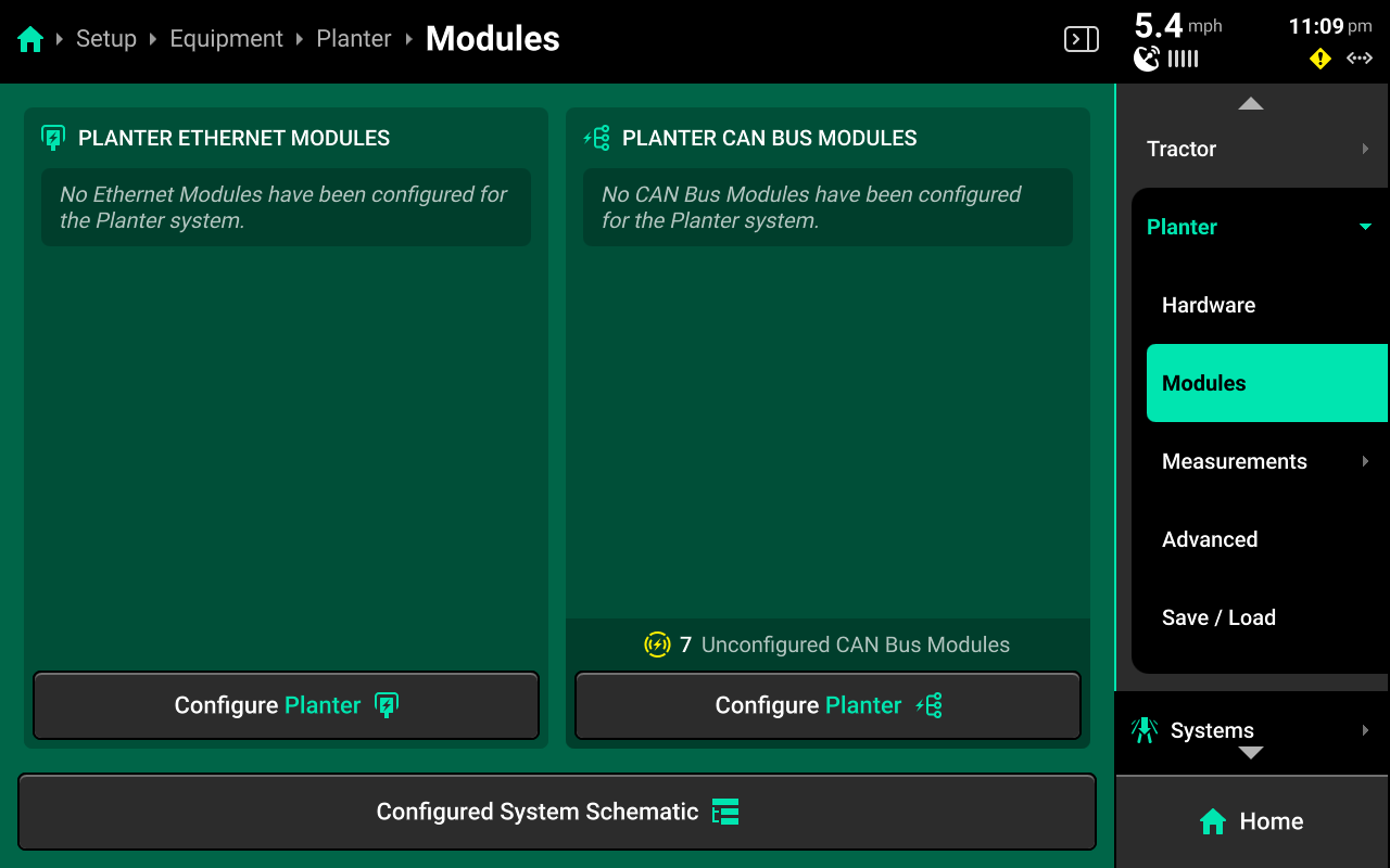
Use the Modules screen to set up Ethernet layout and serial numbers, and CAN module sequence and location.
If the 20|20 is connected to Ethernet or CAN modules and all modules / harnesses are undamaged, then all detected but unconfigured modules will be shown under the left and right windows in the center as pictured above.
CAN modules are only available for configuration on the Implement. Only Ethernet modules may be set up on the Cab.
Press Configure (Implement name / Cab name) in either window to begin setting up Ethernet or CAN modules.
Ethernet Modules
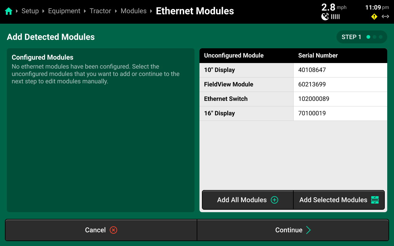
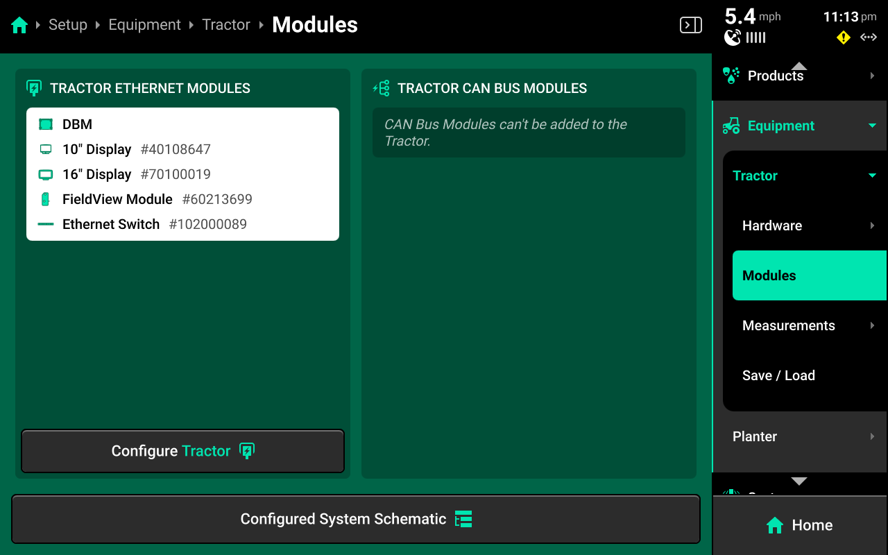
If all Ethernet modules are detected correctly in the left window, press Add All Modules + in the bottom of the right window on Step 1 to confirm and save auto-detected modules. To add only select modules, press each desired module in the left window, then press Add Selected Modules to confirm and save each highlighted module.
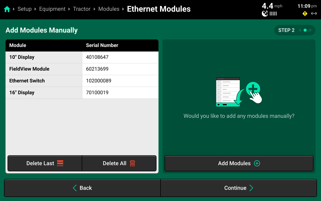
(Optional)
If Ethernet modules will be connected later, modules may be set up manually on Step 2 if desired. When using manual setup, it will be necessary to know the serial number of the manually added modules for the next step. Press Add Modules + in the right window and select the correct module from the popup.
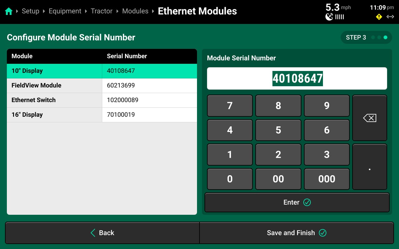
Confirm or enter correct serial number for each device on Step 3. Press Save and Finish to exit setup and return to Modules. Ensure that Ethernet devices are listed correctly below DBM in the left window.
Ethernet modules may also be added to the implement. This is intended for Ethernet switches and Vision cameras. Configure displays on the Cab to ensure correct function.
CAN Modules
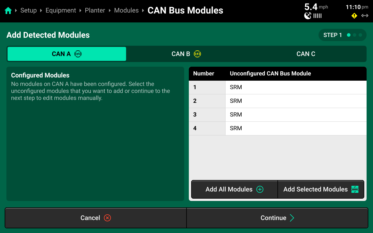
If all CAN modules are detected in the correct sequence in the left window, press Add All Modules + in the bottom of the right window on Step 1 to confirm and save auto-detected modules. Use the tabs at the top to repeat this process for each CAN bus.
It is possible to add only some detected CAN modules by pressing each desired module in the left window and then pressing Add Selected Modules. This is typically not necessary in CAN Module setup if all modules are detected correctly.
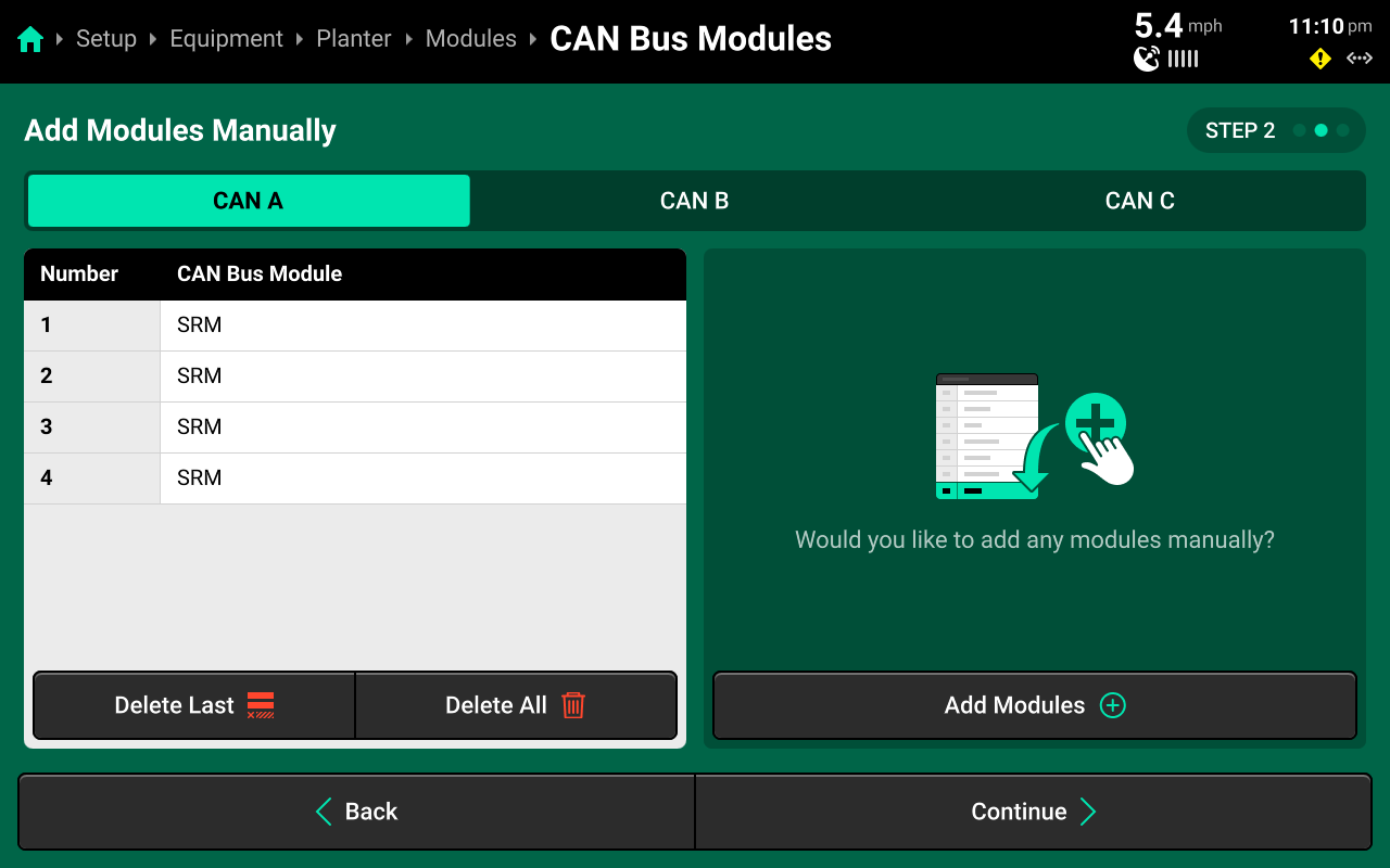
(Optional)
If CAN modules will be connected later, modules may be set up manually on Step 2. Press Add Modules + in the right window and select the correct module from the popup, then select the correct number of modules in sequence. Repeat until all modules are added. Then use the tabs at the top to repeat this process for each CAN bus.
Modules must be added in the correct sequence. For example, if a 12 row sensing system on a planter is using an SRM on each row, and a Smart Connector installed between rows 6 and 7, the user must add:
6xSRM > 1xSmart Connector (SC) > 6xSRM.
The FCIM is a Fendt Momentum-specific module. It will always be added after the first (PDM) SRM on CAN A.
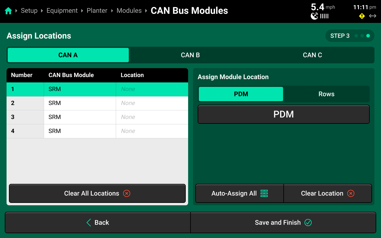
For standard planter configurations, press Auto-Assign All in the left window to automatically assign the correct location to each CAN module in sequence, starting with PDM (if set to present) or Row 1 (if PDM is set to not present). Then use the tabs at the top to repeat this process for each CAN bus.
When configuring a sprayer boom, CAN B will auto-assign from right to left.
Alternatively, select the correct location for each module using the table in the left window. Use the tabs at the top of the table to toggle between types of location. Making a selection will automatically jump to the next module in sequence. Press Clear Location in the left window to erase the location for the module selected in the right window. Press Clear All Locations in the right window to erase all locations for the current CAN bus.
Configuration Review
Press Save and Finish after confirming correct module sequence / location to return to Modules.
Daisy chain breaks and damaged harnessing will cause the auto-detect feature to function improperly. Review the summary listed under Implement CAN Bus Modules to ensure the correct number of Bus devices were detected / added.
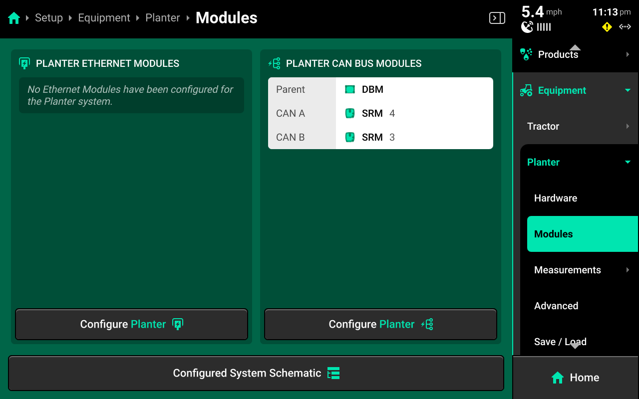
Press Configured System Schematic at the bottom to view a schematic of the configured CAN bus(es)
Seeding / Fertilizer Rank Air Seeders
For Air Seeders which utilize both Seeding and Fertilizer Ranks, there will be two separate Module menus. Any rank may be set up using any CAN bus, but CAN buses may not cross ranks (e.g. if the user sets up CAN A on the Seeding Ranks, CAN A may not also be used on the Fertilizer Ranks. The same is true for CAN B & C).
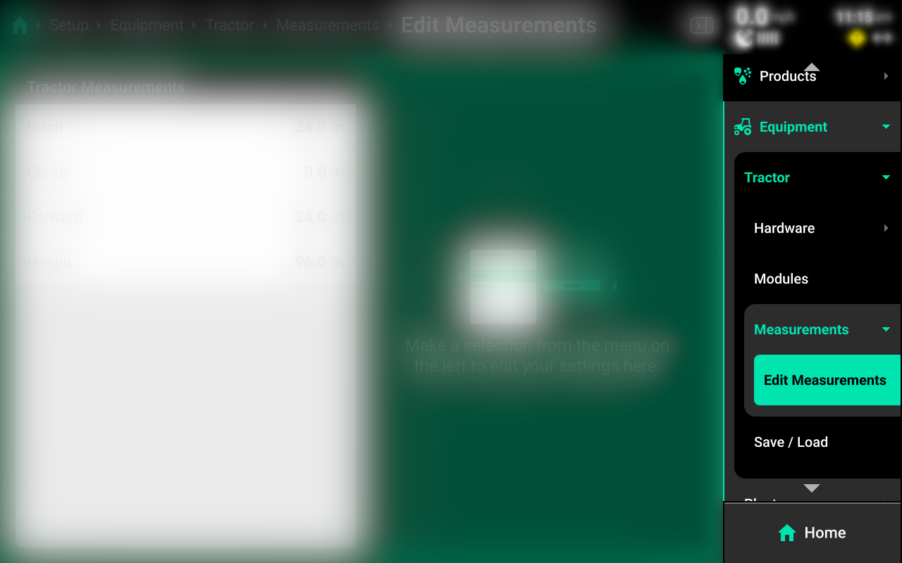
Measurements
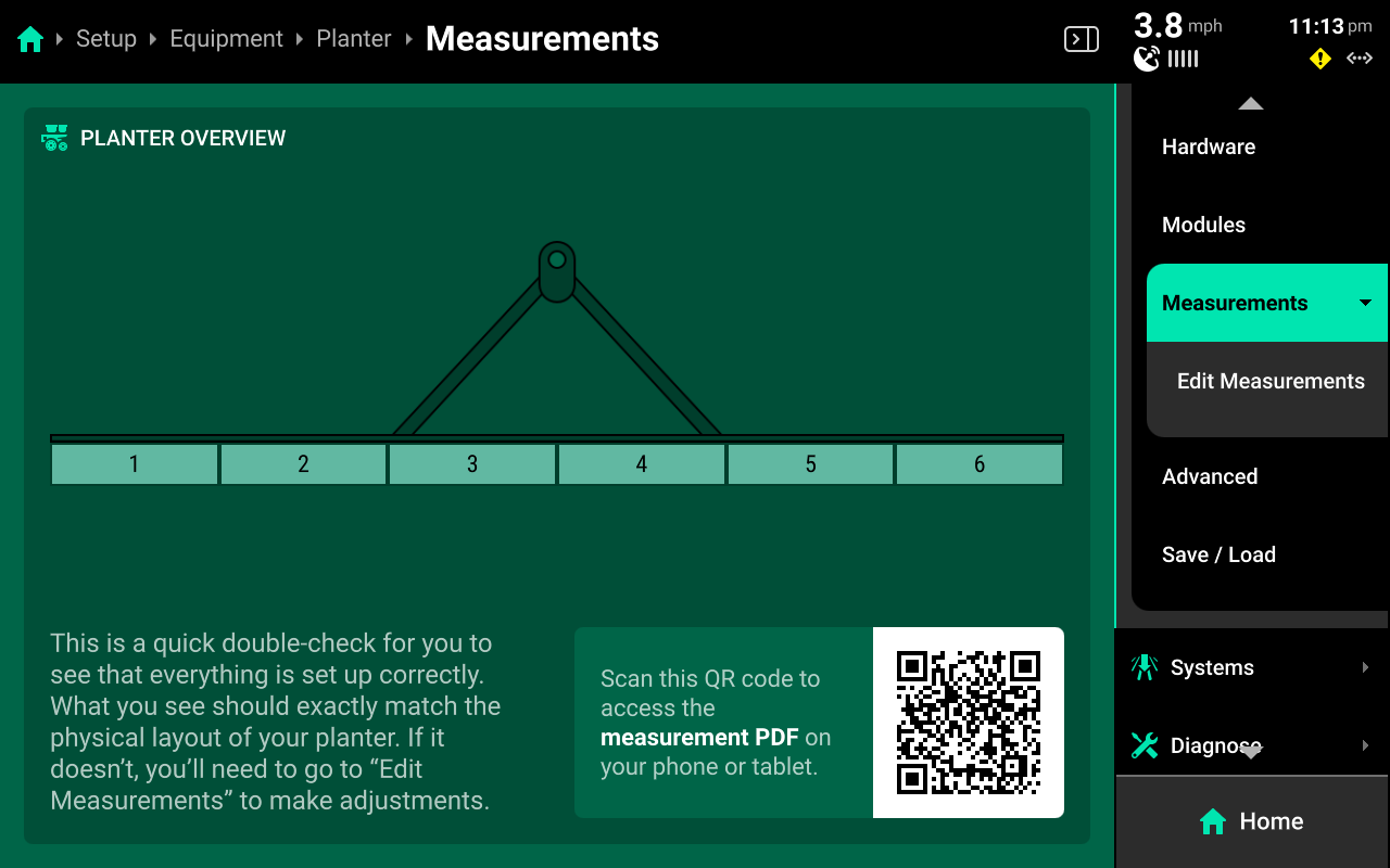
Use the Measurements screen to enter all Cab / Implement measurements.
The Measurements Landing Screen displays a QR code which will open a form-fillable, printable .pdf worksheet to assist with recording measurements, and a Frame Layout for the Implement.
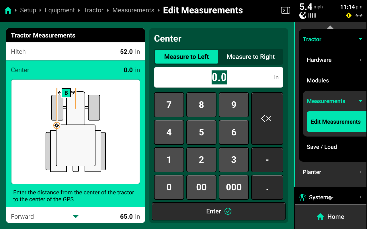
Edit Measurements
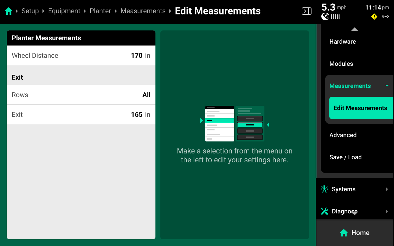
Select the desired dimension in the left window and use the right window to modify the dimension. Some dimensions will expand in the left window when pressed to display a graphic indicating what to measure. Continue scrolling after entering a value to view all available dimensions.
Some dimensions have a Measure to Left / Right toggle in the right window. A value must be entered and saved using the keypad before the toggle will function.
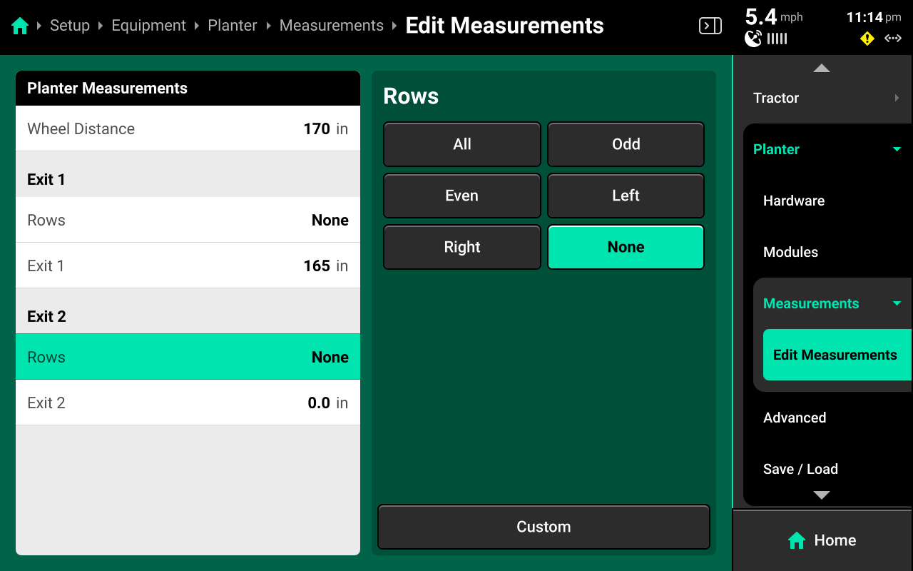
When configuring an Implement with multiple seed / application exits, set all rows for each exit to None before selecting the rows for any exit.
Advanced
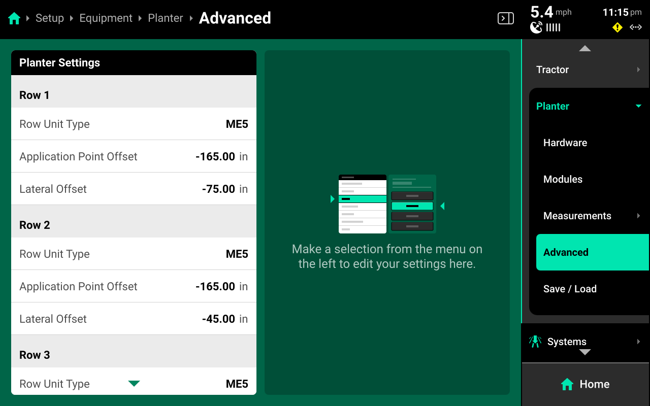
Implements will display the Advanced option in the Navigation Menu when Advanced Frame Type is selected on the implement profile. The Advanced screen allows the user to set the Row Unit type (planter only) for each row individually. Use this feature on mixed-row unit planters to ensure correct system operation. Ensure to select Advanced for Frame Type / Boom Type if utulizing the Advanced table.
It will be necessary to also select the correct load cell for each row unit if running DeltaForce or AirForce on all mixed-row unit planters.
This screen also allows the user to enter custom Application Point (front-to-back) and Lateral (side-to-side) offsets for each row or nozzle.
To streamline setup when using the Advanced table, first navigate to Setup > Equipment > [Implement Profile] and select the Frame / Boom Type that most closely resembles the physical implement. Proceed to Edit Measurements and assign rows / nozzles to the different exit points. Then return to the Implement profile and switch the Frame / Boom Type to Advanced. This will give each row / nozzle a default value in the Advanced table, rather than starting from 0.
Save / Load
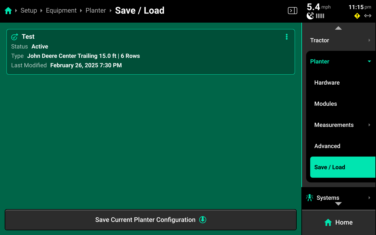
Use the Save / Load screen to save, update, and quickly switch between different Implement profiles. A table of all saved profiles of the current type are displayed in the center. Press Save Current (Equipment Name) Configuration at the bottom to save the current Product / Equipment / System / Home Screen configurations with the desired name.
Press the ![]() Icon on any profile in the table to Load, Update, or Delete the profile. Update saves any current changes to the selected profile.
Icon on any profile in the table to Load, Update, or Delete the profile. Update saves any current changes to the selected profile.
 Systems
The Systems menu is used to configure all Precision Planting control and sensing hardware, System Alerts, swath settings and control sections. The user may also use the Systems menu to adjust Operation Settings for hardware, such as disabling failed sensors and enabling overrides.
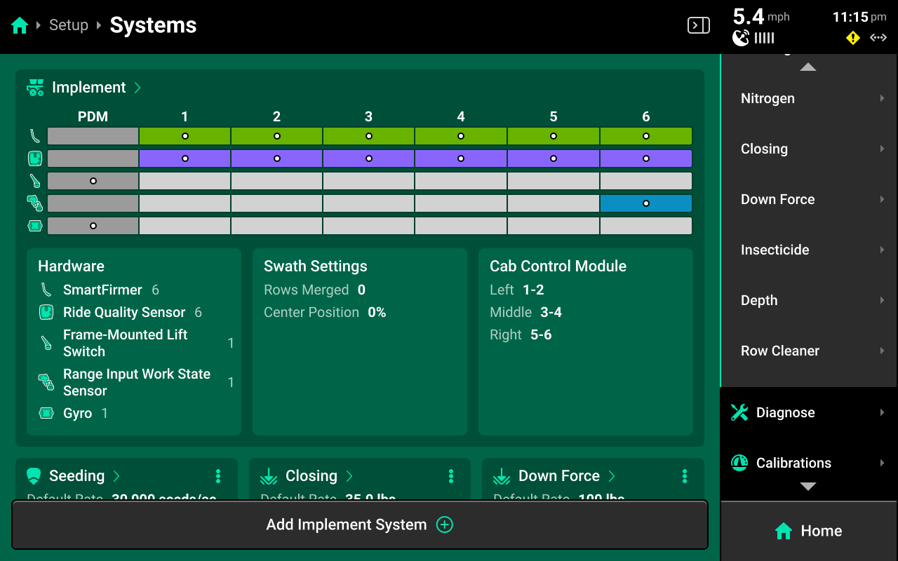
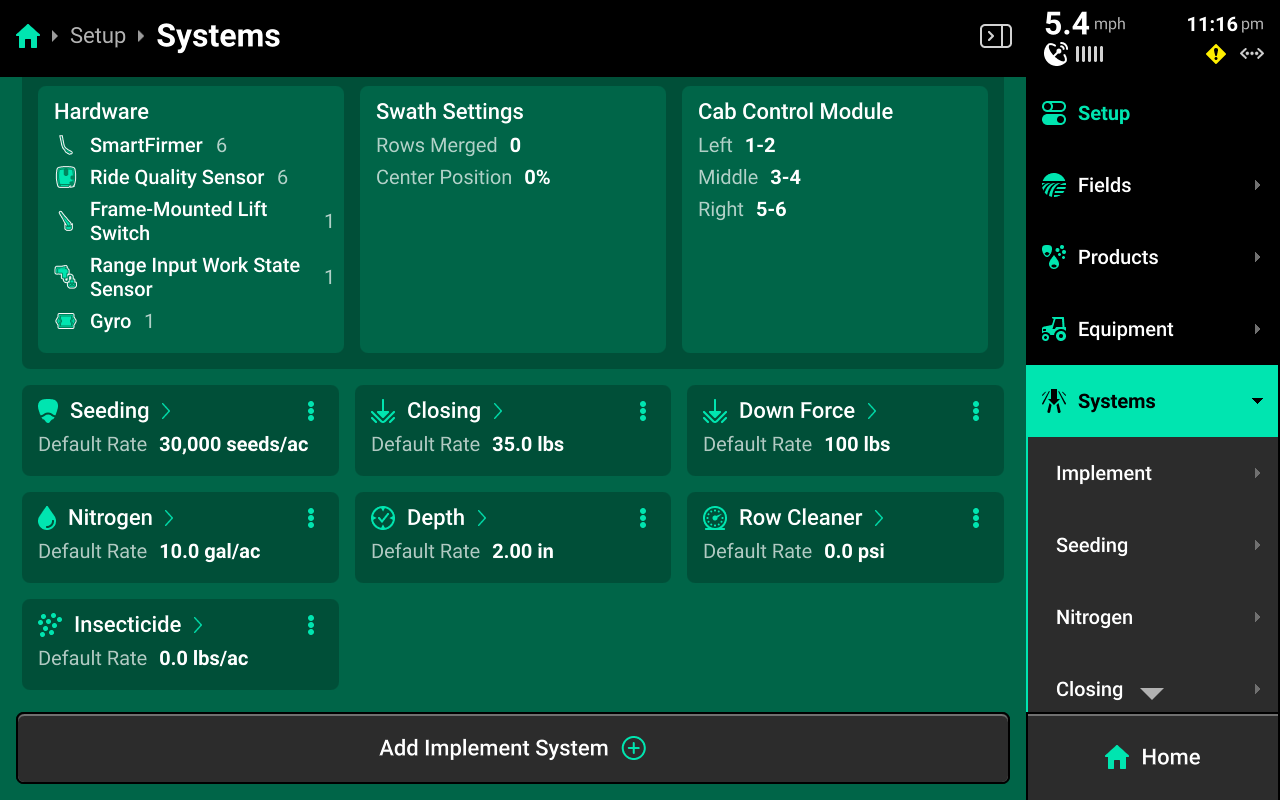
There will be a default system which is either named after the type of Implement profile selected in Equipment, or simply titled Implement. This system is where all implement level hardware, such as lift switches and SmartFirmers, will be configured. All other hardware is added in its respective System, which starts by pressing Add Implement System at the bottom of the Systems Landing Screen.
The System Landing screen also displays an overview of default system hardware, a summary of swath and CCM settings, and a list of all control and sensing systems which have been configured.
This guide will detail general system information and basic setup. Refer to all applicable operator's guides for system-specific configuration, parameters, and settings.
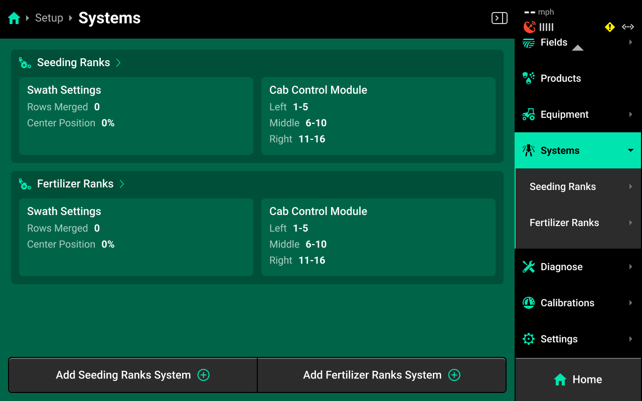
If Air Seeder with Fertilizer and Seeding Ranks is the selected Implement, there will be two default systems named Seeding Ranks and Fertilizer Ranks. Each control / sensing system must be added under the appropriate set of ranks by pressing either Add Seeding Ranks System or Add Fertilizer Ranks System at the bottom.
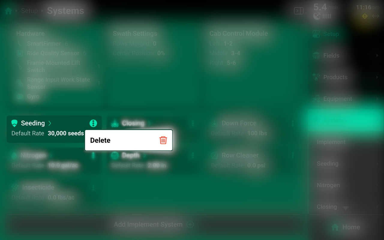
Adding / Deleting a System
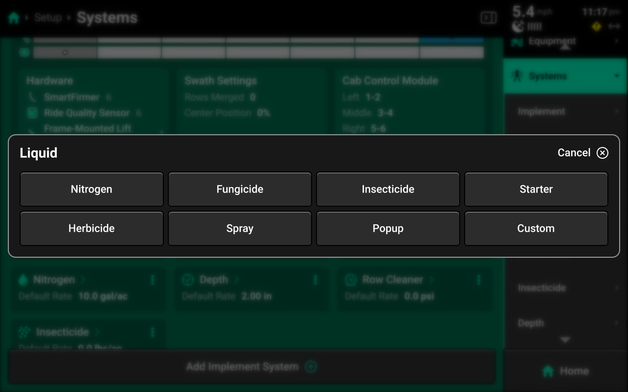
Pressing Add Implement System will open a popup that allows the user to select the Type of system.
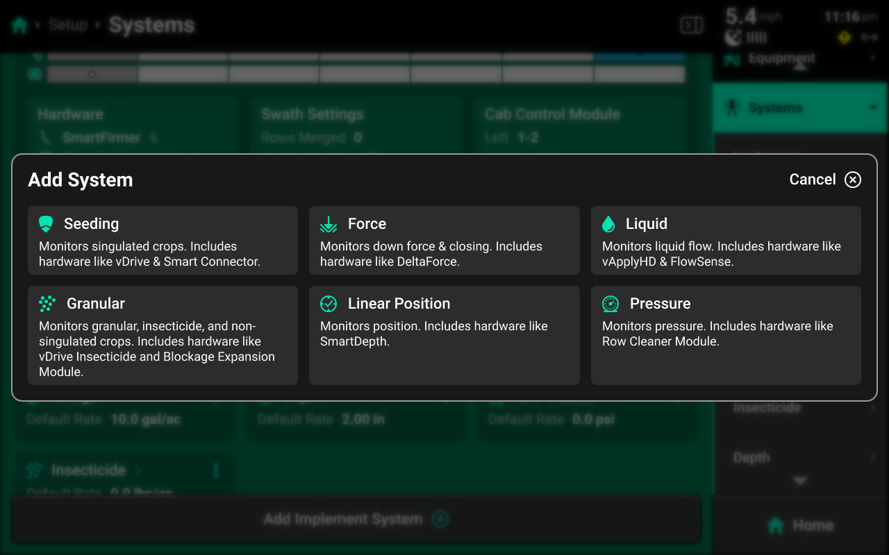
Selecting the type of system opens a second popup which allows the user to select a preset Name or enter a custom Name. It is advised to add all systems before proceeding to Hardware Setup.
Press the ![]() Icon next to any system in the center to delete it.
Icon next to any system in the center to delete it.
Once all systems have been added, select a system in the Navigation Menu or press a system name in the center to navigate to that system screen.
All system Names are placeholders only and do not determine available hardware. Available hardware is determined by system Type. Ensure to configure all appropriate hardware in the desired system. Do not configure multiple system's hardware in one system. Doing so will cause all hardware devices to malfunction.
Implement (Default) System Settings
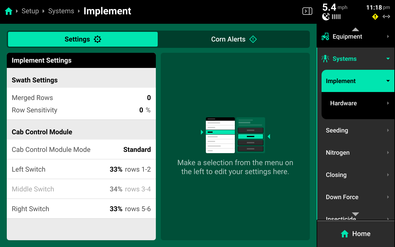
Use the left window on the Implement (Default) system screen to view system settings.
Swath Settings
Press Merged Rows in the right window, then press Edit Swath Settings in the right window to tie end rows together using a setup wizard. Select the number of rows to merge on Step 1.
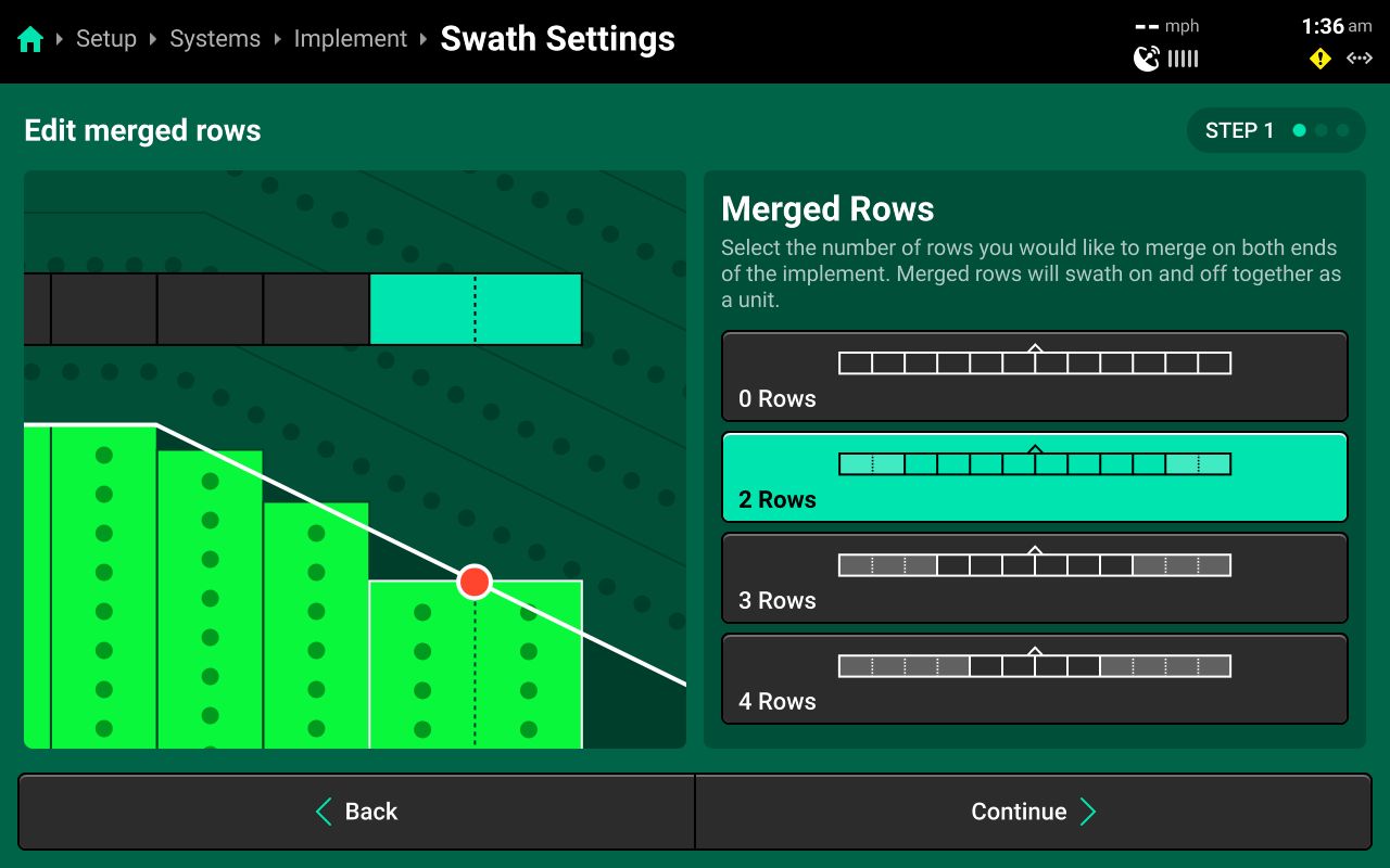
Step 2 (optional) allows the user to enter a positive or negative value to change the point that the 20|20 will use as the center of the merged section. Review choices on Step 3, then press Save and Finish.
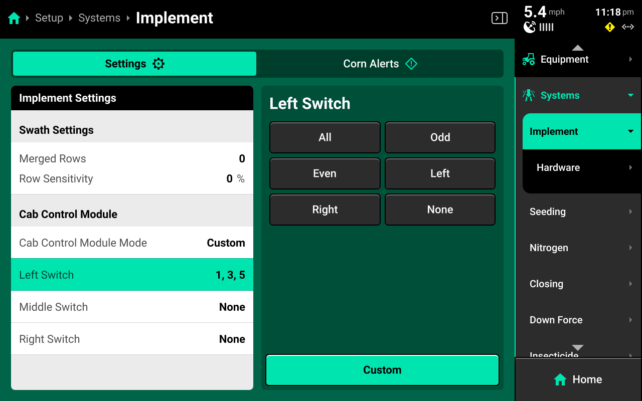
CCM Settings
The 20|20 will assign approximately 33% of the implement rows to each switch on the CCM. Press Cab Control Module Mode in the left window and select Custom in the right window to manually assign rows to each CCM swath switch. Select each switch in the left window, then select a preset option in the right window, or press Custom in the bottom right window to assign custom rows to each switch.
Other Systems
Other systems will have different settings available in the left window depending on system Type. Each of these settings are system specific. Typical settings are detailed here.
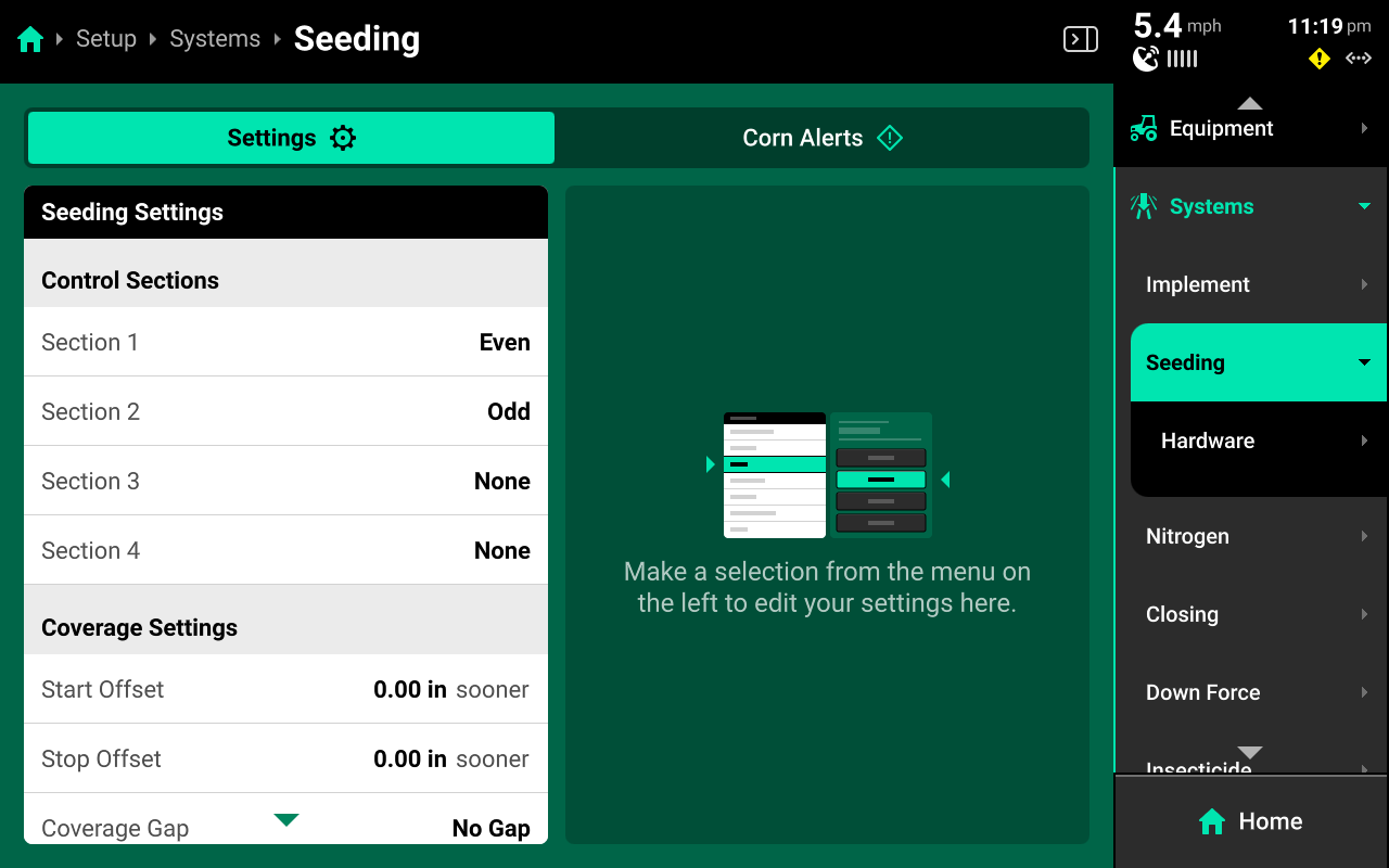
Control Sections
Used to set up different rate sections. The rates for each control section are adjustable individually or collectively using the system Control widget on the home screen.
Start / Stop Offsets
Used to fine-tune swath timing by commanding the selected system to start or stop applying sooner or later.
Coverage Gap
Used to determine the gap between the swath on / off point and previous coverage. This will be affected by any Start / Stop Offsets.
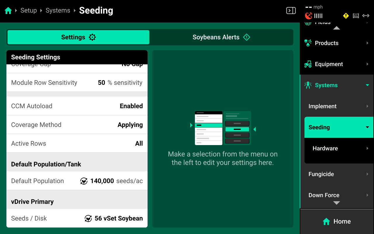
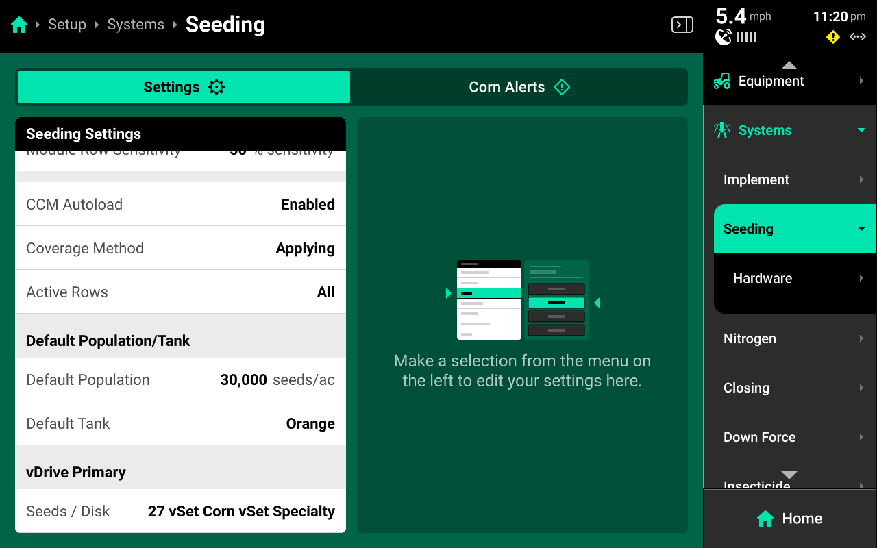
Module Row Sensitivity
Used to determine when a module which applies product across multiple rows (e.g. vApply Base) will swath on / off.
CCM Autoload
Used to enable / disable autoloading for the system. Any system with this setting enabled will dispense product when the left and right swath switches on the CCM are clicked up.
Coverage Method
Used to determine when the 20|20 will build Coverage. Any system set to Work State and Applying will not map Coverage unless the lift switch reads lowered. Population and other application maps will still build.
Active Rows
Sets the active rows for the system. System hardware on any rows not set to active will be deactivated.
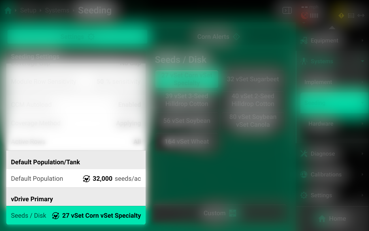
Default Population / Rate
Sets the out-of-prescription and autoload rates for the selected system.
Operation Settings
Other critical hardware settings will be available once system hardware has been configured. See the following section of this guide for more information on Operation Settings.
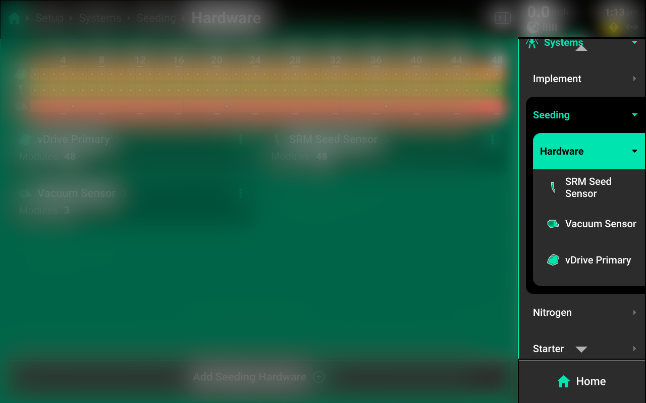
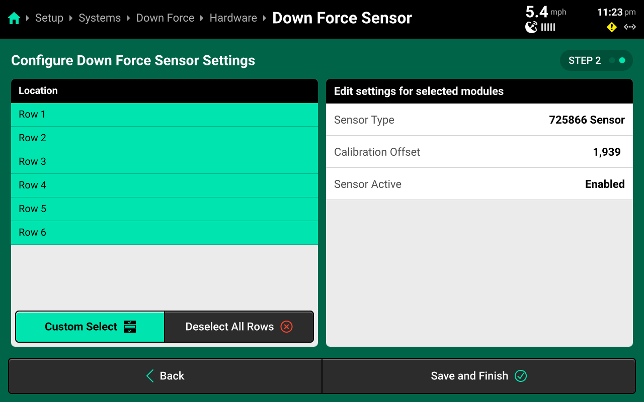
Hardware Setup
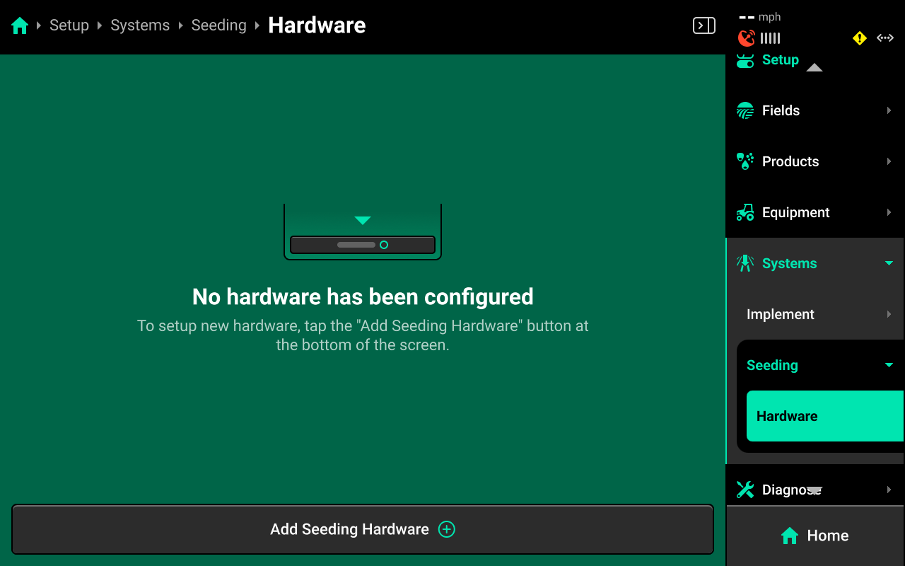
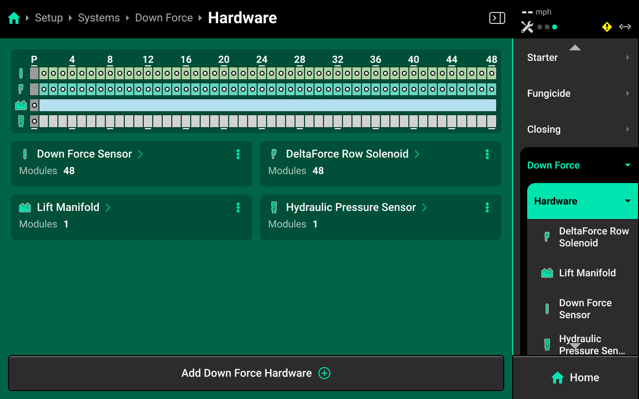
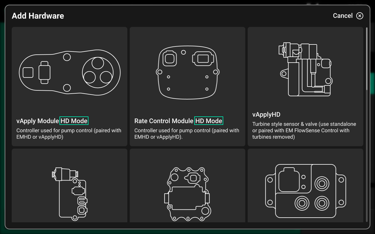
Press Hardware below each system in the Navigation Menu to set up that system's hardware. Press Add (System Name) Hardware at the bottom to open a popup which allows the user to select the desired hardware device.
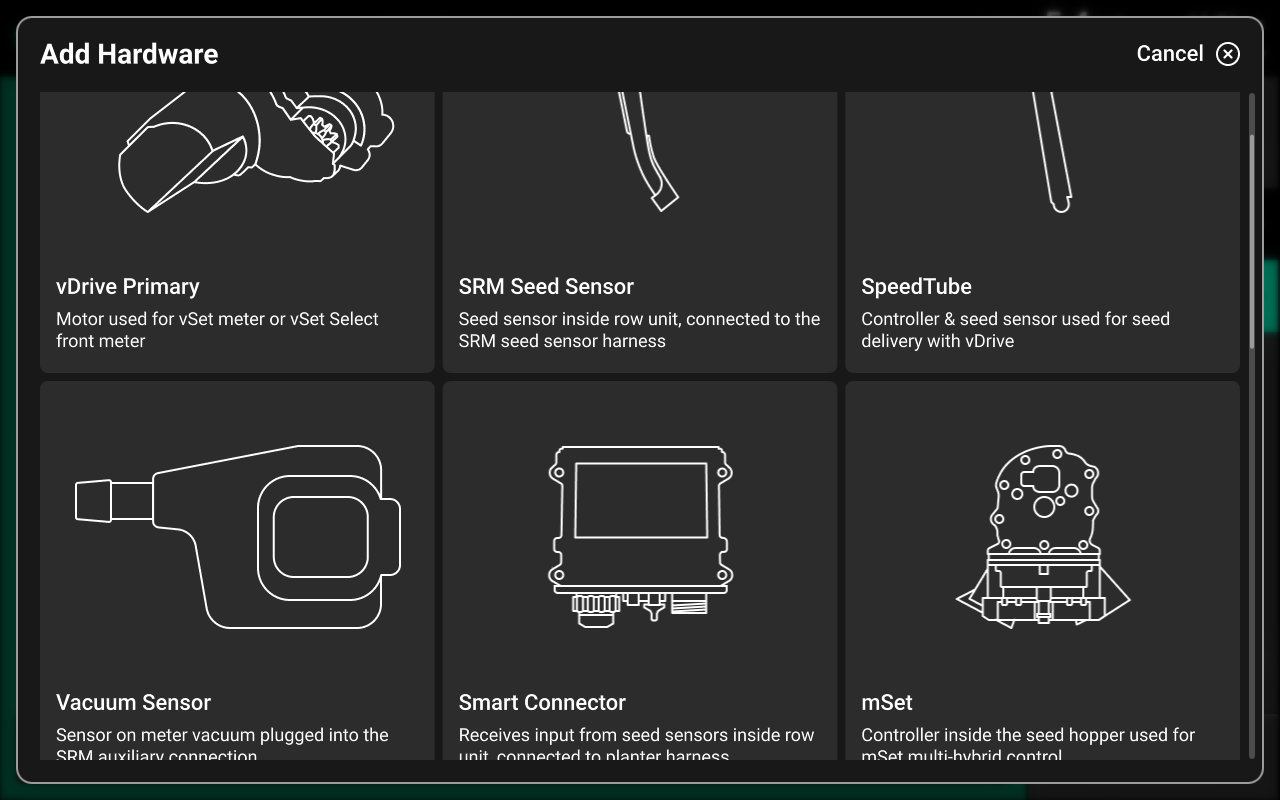
Selecting a device will automatically open the setup wizard for that device. Some hardware setup wizards will have more steps than others.
A list of all configured hardware devices will be displayed in the center of the screen.
Press the ![]() Icon next to any hardware device to delete it or Edit Locations, which will run through the setup wizard again.
Icon next to any hardware device to delete it or Edit Locations, which will run through the setup wizard again.
Hardware Settings
Hardware settings are divided into Install Settings, which are typically adjusted during initial setup, and Operation Settings which may be adjusted multiple times per season / year.
Install Settings are accessible on the final step of each hardware setup wizard, and on the specific system hardware screen after that hardware device is added.
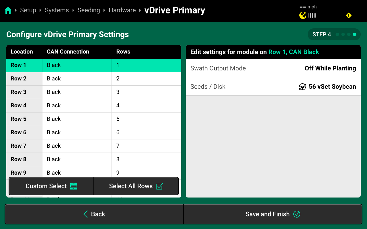
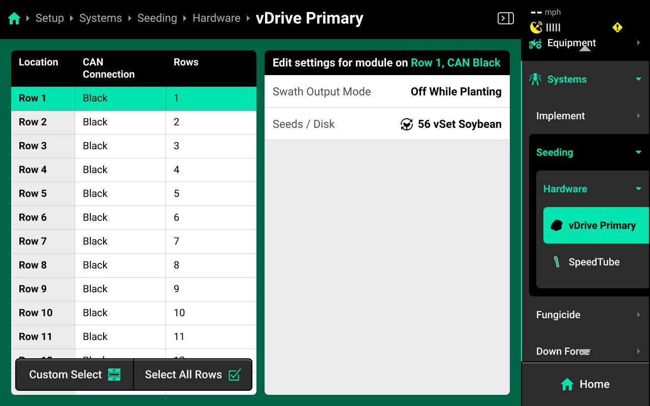
Operation Settings are accessible from the left window of the specific system screen after the hardware device is added. It may be necessary to scroll to view all Operation Settings.
Some Operation Settings (e.g. vDrive seeds / disk) are also available under the System Settings tab on the Field Setup screen.
Hardware Setup Tips
-
Any device which doubles as a CAN Module (e.g. Smart Connector, BXM, vApplyHD Flex, NCM, etc.) must have the same location assigned to it during both Module and Hardware setup.
-
Access all Install Settings by selecting the specific hardware device after it has been added under the desired system in the Navigation Menu.
-
When assigning jumper colors, Install Settings, or Operation Settings, only the first hardware device is selected by default. When changing a jumper color or setting for all hardware devices of one type, ensure to press Select All Rows in the left window before changing the setting.
- Ensure to select the correct module Mode (e.g. Select vApply Module / Rate Control Module HD Mode if adding a vApply or Rate Control Module to system with vApplyHDs).
Alerts
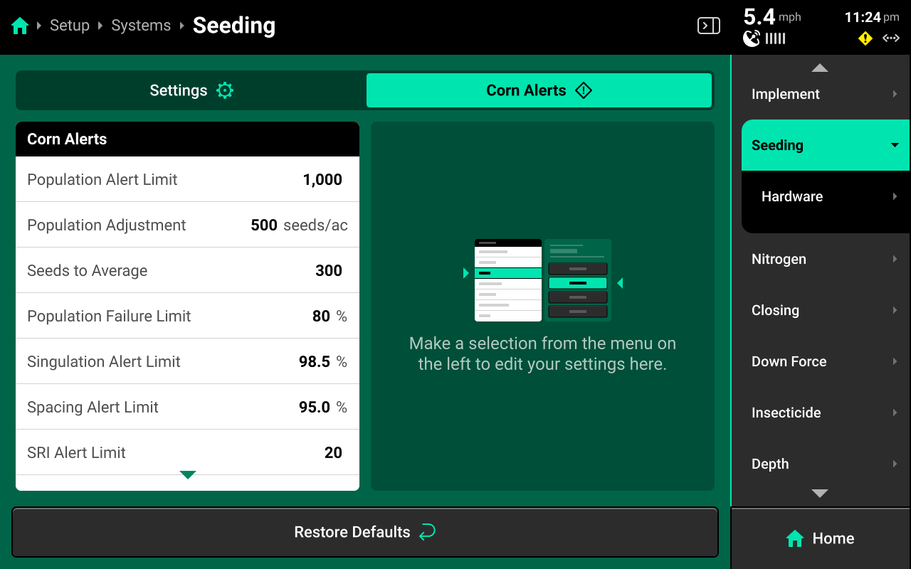
Use the tab at the top of each system screen to view the crop-specific alerts for that system. Some alerts are adjustable by default, others require the corresponding hardware to be added first. It is advised to add all system hardware before configuring alerts for ease of use. All crops have the same default alert settings, but any changes made will be saved to the specific crop. Press Restore Defaults at the bottom to reset crop alert settings.
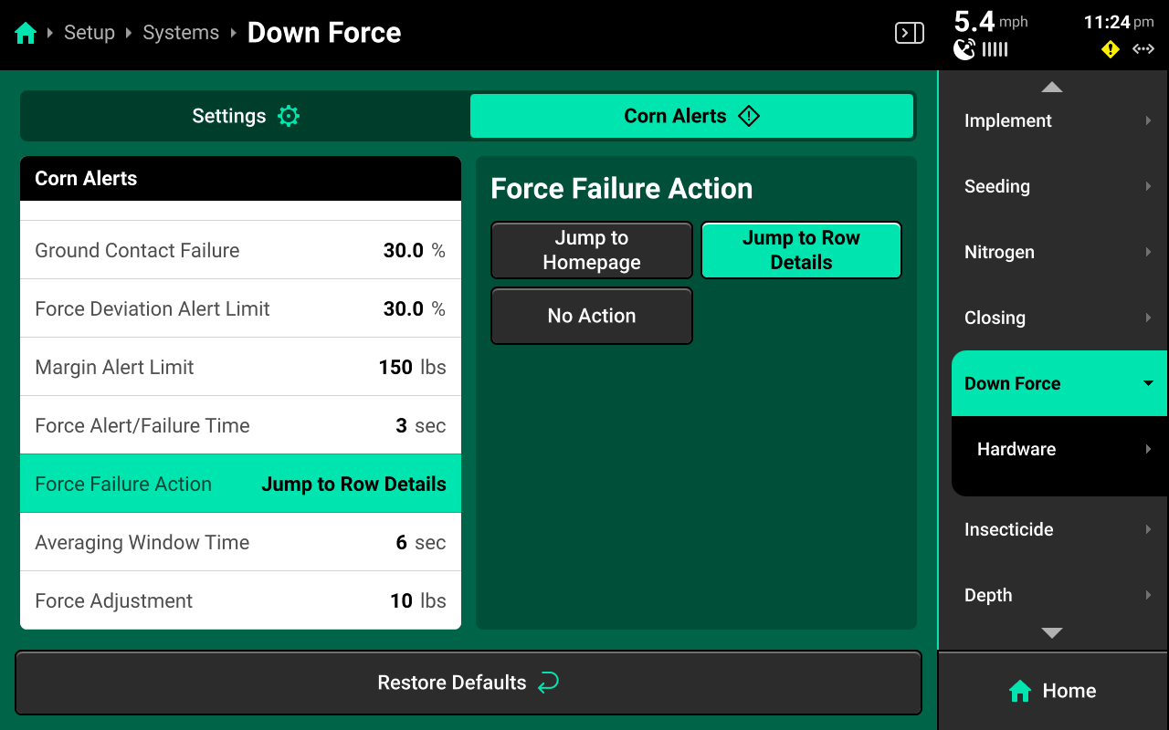
Some alerts contain both Alert and Failure limits. The 20|20 will display a popup notification when alert limits are reached, and will perform the action selected for Failure Action when failure limits are reached. See Display for details on changing alert sounds.
Many systems will have a Population / Rate Adjustment in the left window of Alerts. Change this value to determine the amount that the + (rate) / - (rate) buttons on the system control screen will use.
Many systems will have a Population / Rate Alert Limit in the left window of Alerts. Change this value to determine the scale that is shown on the right of the DMC.
 Diagnose
The Diagnose Menu is used to identify and troubleshoot hardware device failures and configuration issues in the 20|20.
Use the following colors to determine device status on the Diagnose screen.
- Green : Device is working correctly. Communications are good.
- Yellow : Device or sub-component is not 100% functional or is uncalibrated.
- Red : Device has failed, or is expected and not detected.
- White : Device is detected but not expected.
- Black : Device has been disabled by the user.
- Grey : Device is finishing detecting or unreachable.
- Teal : Device is updating firmware.
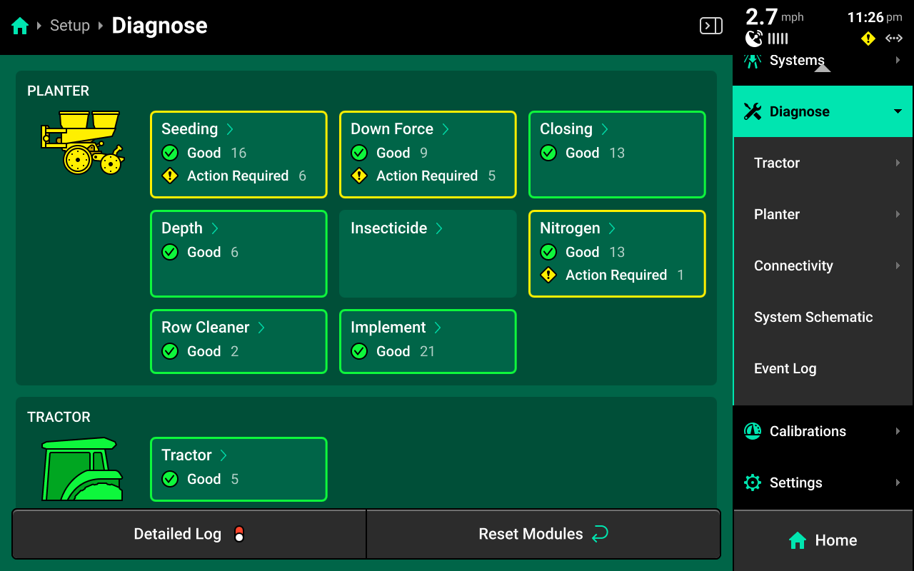
Landing Screen
The Diagnose Landing Screen displays an overview of overall Implement and Cab system health.
Unexpected Hardware
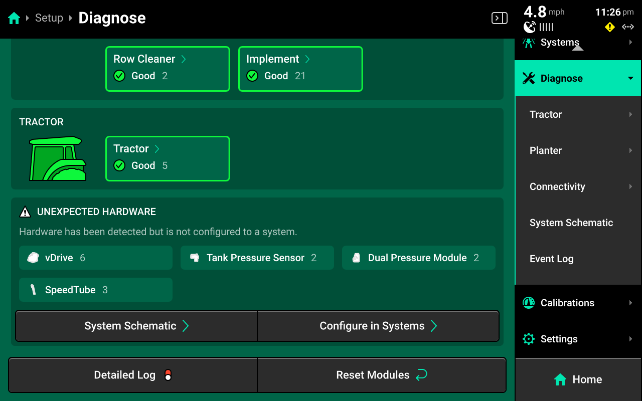
Scroll down on the Diagnose Landing Screen to view a list of all Unexpected Hardware. Unexpected hardware is defined as any CAN / Ethernet Module or Hardware device which the 20|20 detects but has not been configured by the user. Press System Schematic below to navigate to the System Schematic, or press Configure in Systems to navigate to the Systems Landing Screen.
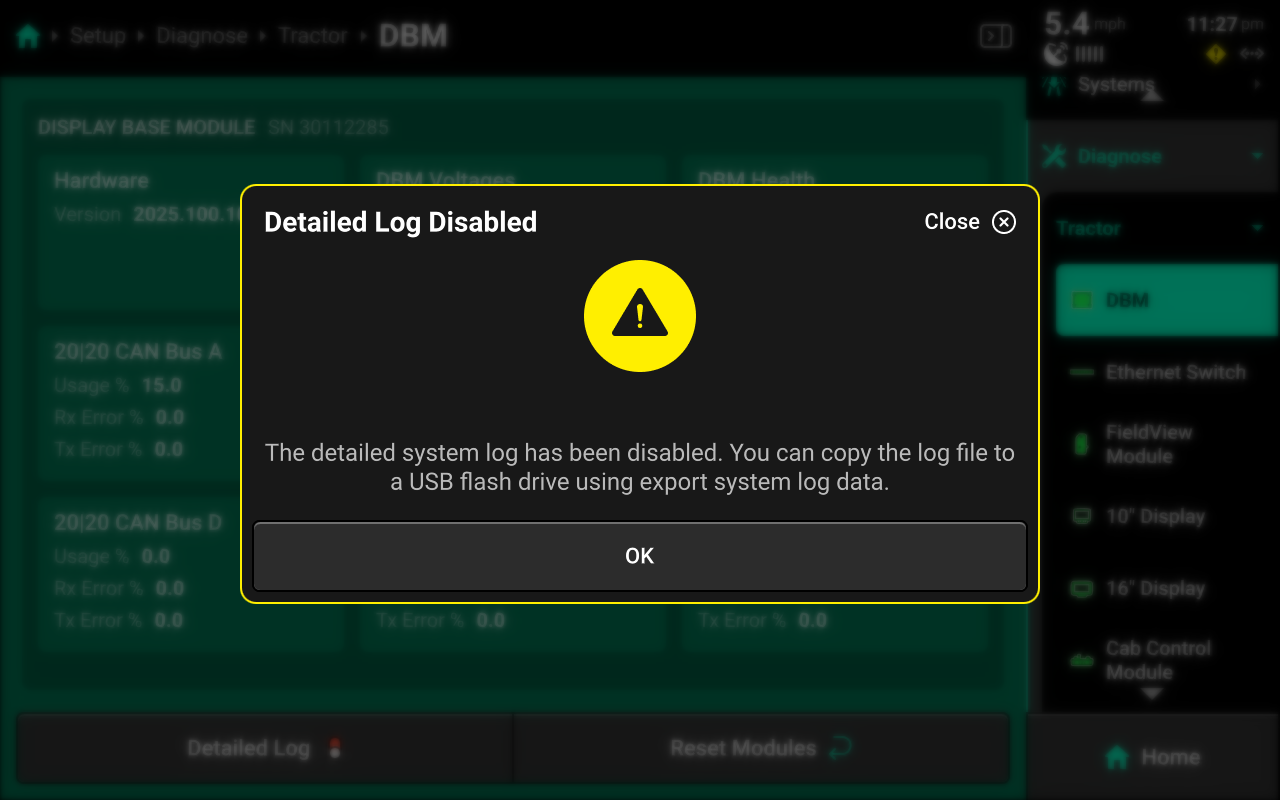
Detailed Log
Press Detailed Log at the bottom of the Diagnose Landing Screen to enable a system log which records all CAN traffic and other data related to 20|20 operation for 60 seconds, after which recording is automatically disabled.
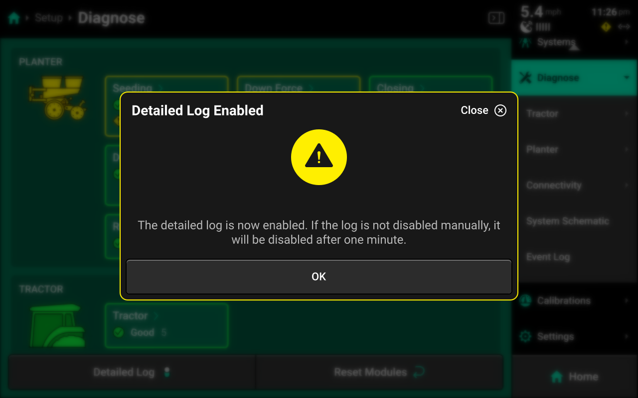
Precision Planting Product Support may require a detailed log when assisting the user with advanced troubleshooting. Detailed logs may be exported to an external USB drive. See Export Data for more details.
Reset Modules
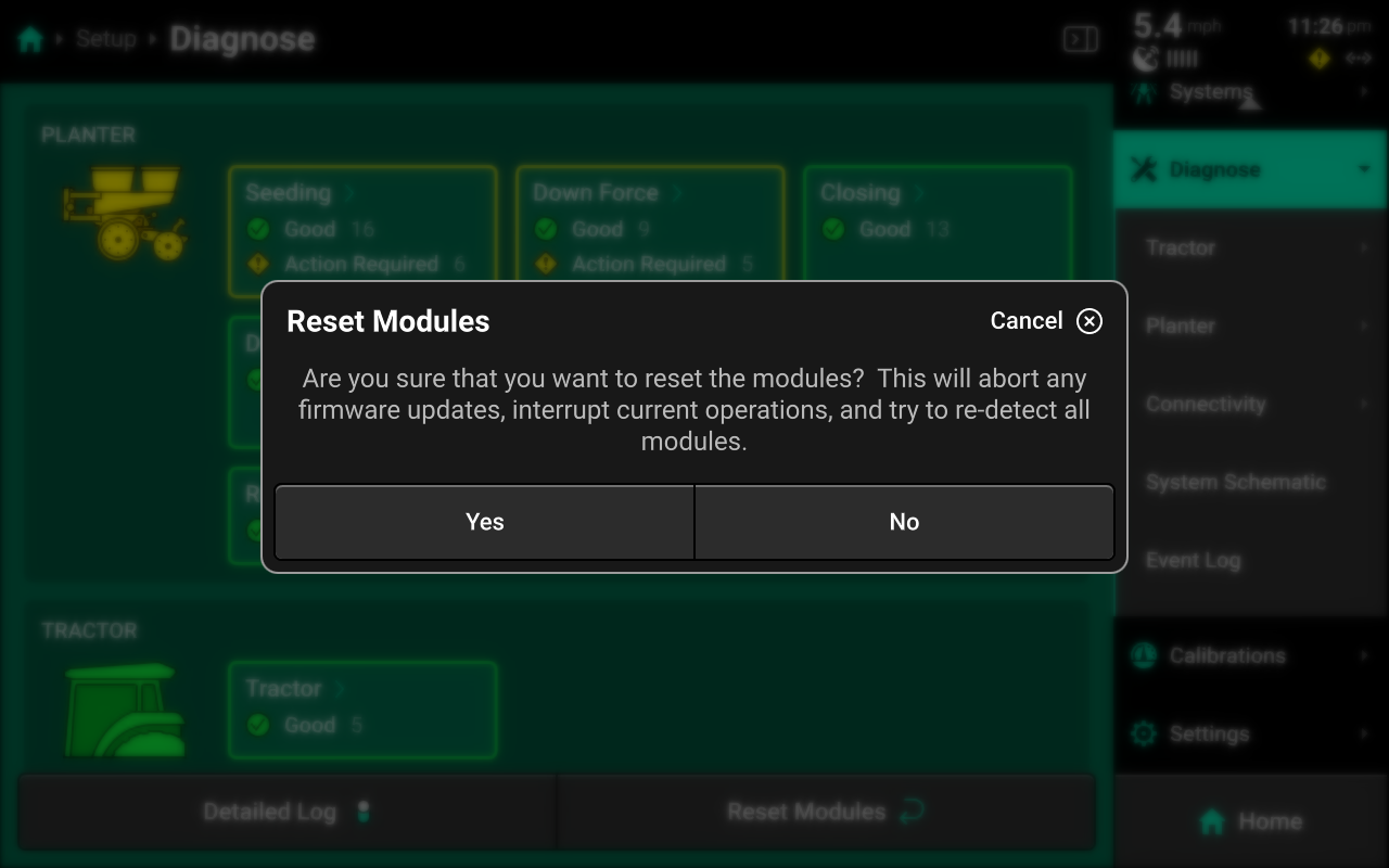
Press Reset Modules at the bottom and confirm on the popup to break and reestablish all CAN communication and daisy chain identification. This function is often used as a troubleshooting tool for communication issues.
Due to programming changes for sprayer and seeder compatibility, after pressing Reset Modules or power cycling in software versions 2023.1.0 and above, if a daisy chain break is present in the physical harnessing, all components after the daisy chain break will display red on the diagnose page. The break must be addressed before implement functionality is restored.
Cab
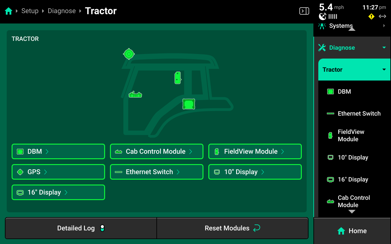
The Cab section of the diagnose menu will share the same name as the Cab profile that is selected in Equipment. A graphic of the Cab and all devices / modules that are installed on it will be displayed.
Navigate to the desired system by pressing it in the center or the Navigation Menu.
DBM
DBM diagnostics are located under the Cab.
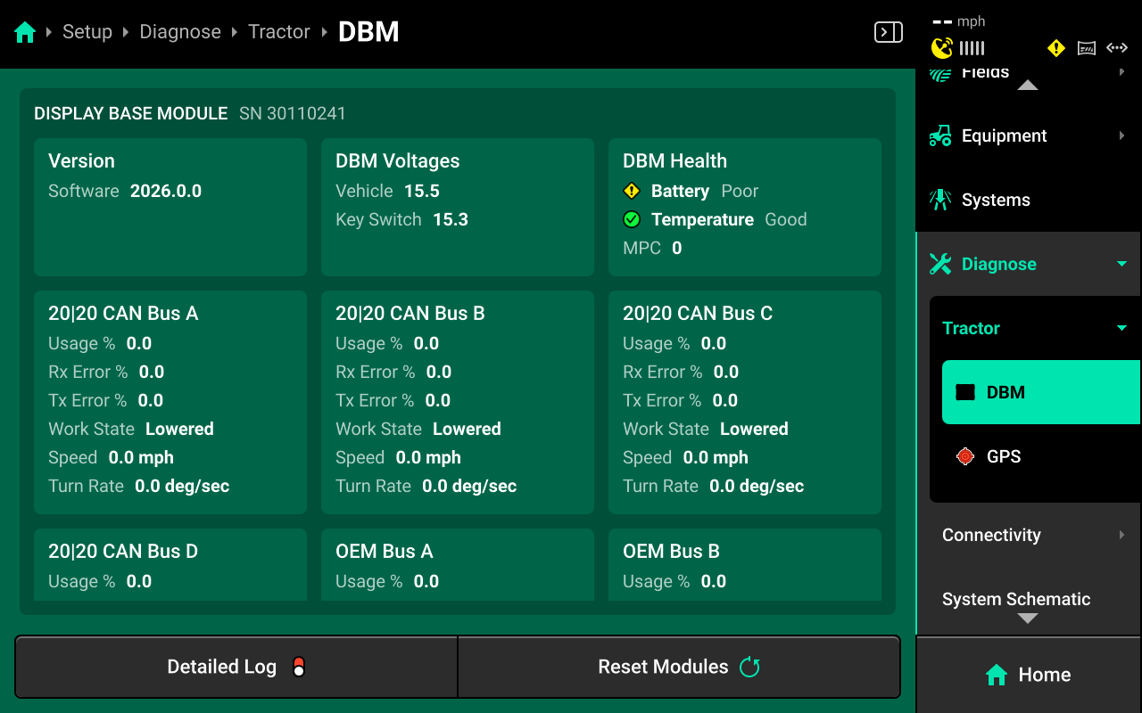
- Version : Software version
- DBM Voltages : Constant and key switch power from power supply to DBM.
- DBM Health : Battery and Temperature status, and Missing Package Correlation
[MPC]. A rapidly climbing MPC value indicates CAN communication issues, such as damaged hardware or harnessing. - CAN A / B / C / D : Displays network usage, percentage of errors in CAN packets sent / received, and work state / speed readings from that CAN bus.
- If usage values exceed 80%, add another CAN network to the implement.
- If Rx / Tx errors are climbing, inspect all CAN components on the corresponding bus for damage / loose connections.
- Incorrect Speed / Work State readings indicate issues with the Equipment configuration. Restart the Gen 3 and key off the Cab to restart the GPS receiver. If readings are still incorrect, delete and rebuild the Equipment profile.
- OEM BUS A / B : Combine mode only. Indicates network usage and percentage of errors in CAN packets sent/received.
Ethernet Switch
Ethernet switches will be displayed on the Diagnose screen under Cab or Implement depending on where they were configured in Equipment setup.
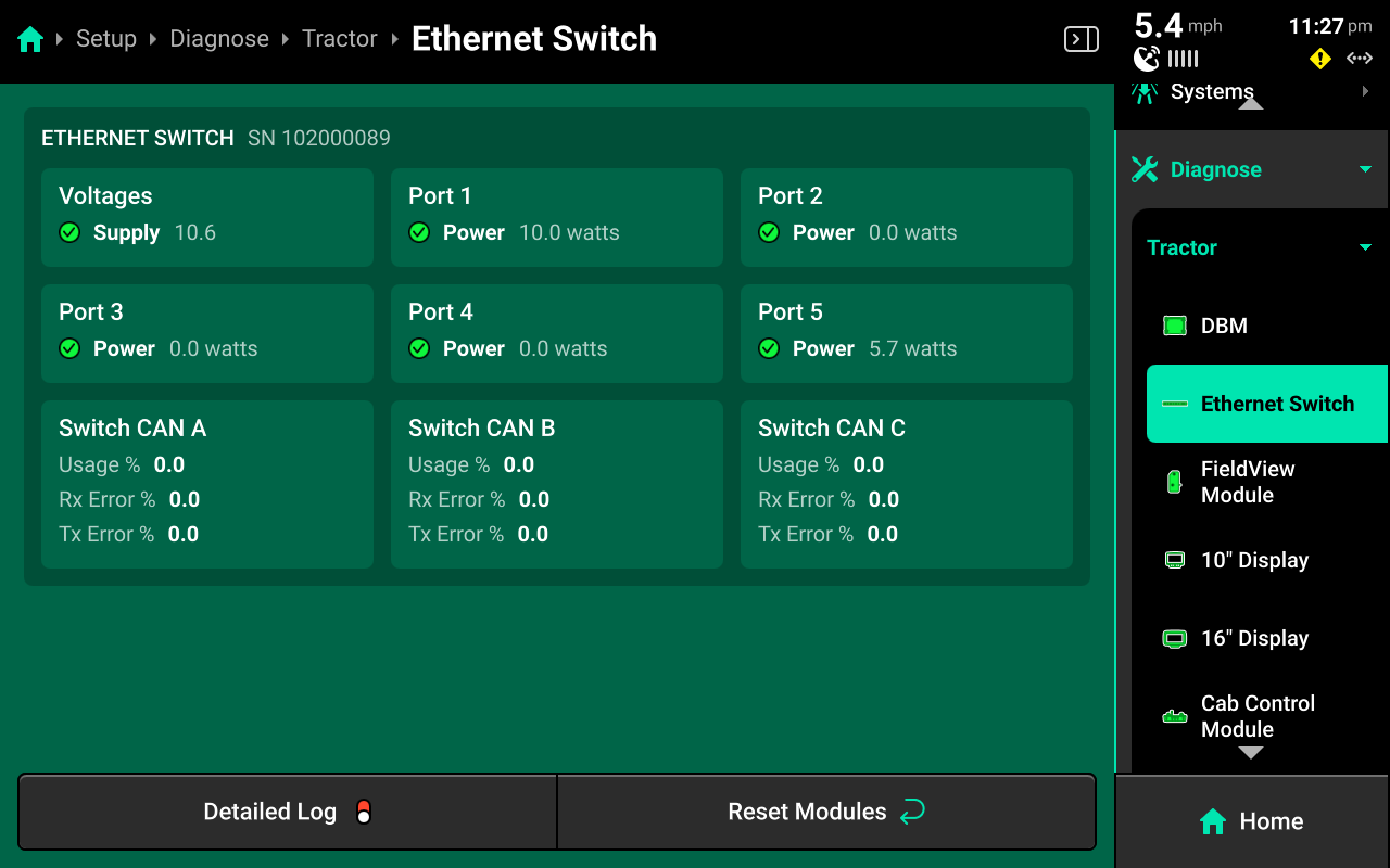
- Voltage : Displays supply voltage to the Ethernet switch.
- Port 1-5 : Displays POE status for the indicated Ethernet port.
- Switch CAN A / B / C : Displays network usage and percentage of errors in CAN packets sent / received for each CAN network generated from the Ethernet switch.
- If usage values exceed 80%, add another CAN network to the implement.
- If Rx / Tx errors are climbing, inspect all CAN components on the corresponding bus for damage / loose connections.
- Incorrect Speed / Work State readings indicate issues with the Equipment configuration. Restart the Gen 3 and key off the Cab to restart the GPS receiver. If readings are still incorrect, delete and rebuild the Equipment profile.
FieldView Module
If using a FieldView module [FVM] to connect to the Climate Corporation FieldView cab app and the FVM has been configured as an Ethernet module, FieldView diagnostics and controls will be displayed in the center screen after selecting FieldView Module in the Navigation Menu.
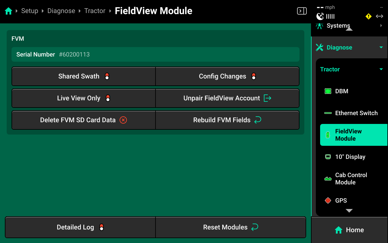
Use the indicator light on the FVM to diagnose connectivity issues. See Indicator Light Overview for more details.
- Config Changes : Enable this setting to allow FieldView to make configuration changes in the 20|20.
Enabling config changes will allow FieldView to push any changes to the 20|20. If a configuration change is made in the 20|20, but not in FieldView, this may result in operation where the 20|20 appears to be deleting configuration details such as tank mix, hybrids, prescriptions, etc. Ensure that any changes made in the 20|20 are also made in the equipment profile equivalents on FieldView as well.
- Shared Swath : Enable this setting to allow swath sharing between two implements in the same field using FieldView.
- Live View Only : Enable this option if using Panorama to send field map data to a FieldView account. Enabling this option will prevent the 20|20 from saving data on the FVM SD card. Maps will still build on the cab app.
- Unpair FieldView Account : Unpairs a connected FieldView account.
- Delete FVM SD Card Data : Deletes all data from the SD card in the FVM. This function will not delete data from the 20|20.
- Rebuild FVM Fields : Uses field data on the 20|20 to rebuild FVM SD card data. The FVM will then sync the rebuilt data to FieldView.
If experiencing connectivity issues between the FVM and iPad, it is often necessary to change the charging and data transfer cable that connects the FVM to the iPad. There are several guidelines for selecting the correct cable.
- For iPads with a lightning port, ensure that the cable is non-counterfeit MFI Certified. This is the only supported cable type.
- For iPads with a USB-C charging port, ensure that the charging cable is rated for data transfer in addition to power charging.
- Ensure to use the shortest cable length possible from FVM to iPad. Data transfer issues increase with cable length.
Display
10" and 16" displays will appear on the Diagnose screen under Cab if configured correctly in Equipment setup.
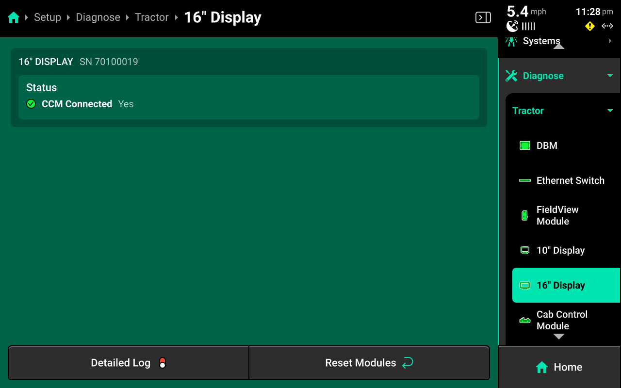
CCM connection status is displayed. Only one display may have a CCM connected. The CCM will be automatically detected.
Cab Control Module
The CCM will be listed below the display to which it is connected.
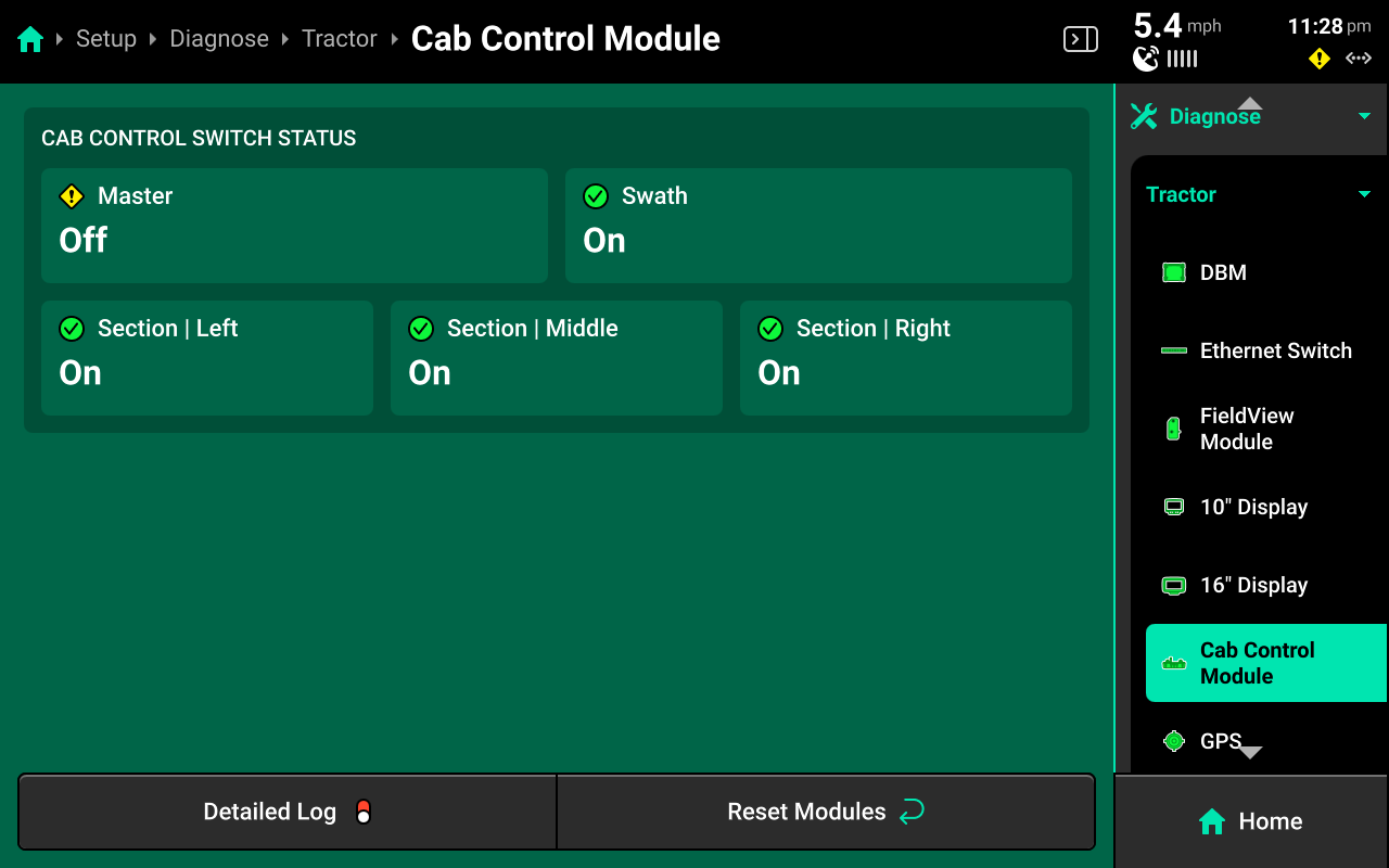
On / Off position for all switches is displayed.
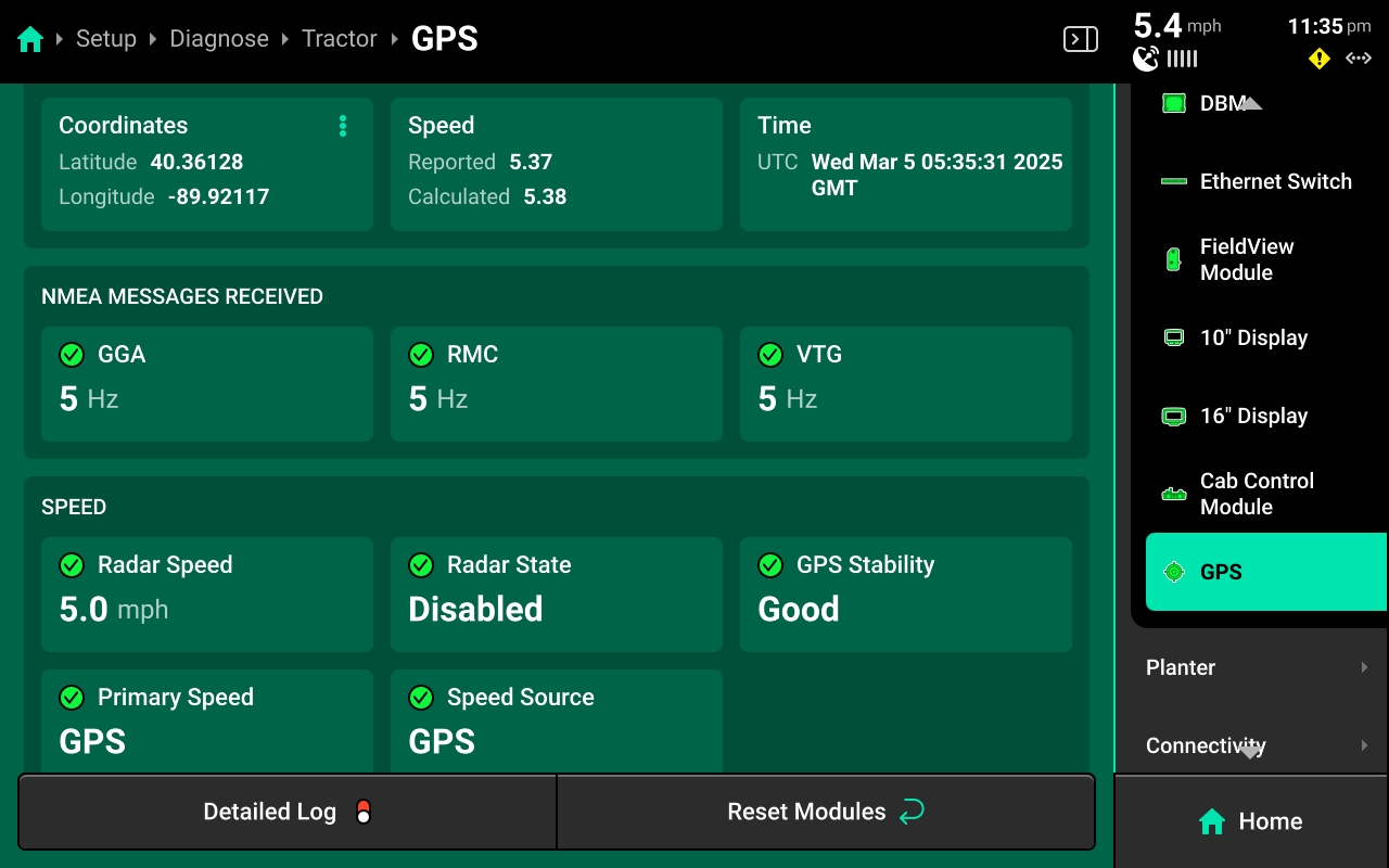
GPS
GPS diagnostics are located under the Cab. GPS will be displayed in red until proper GPS communication is established with the receiver.
If GPS is configured on the Implement in Equipment setup, GPS diagnostics will be listed under the Planter on the diagnose screen.
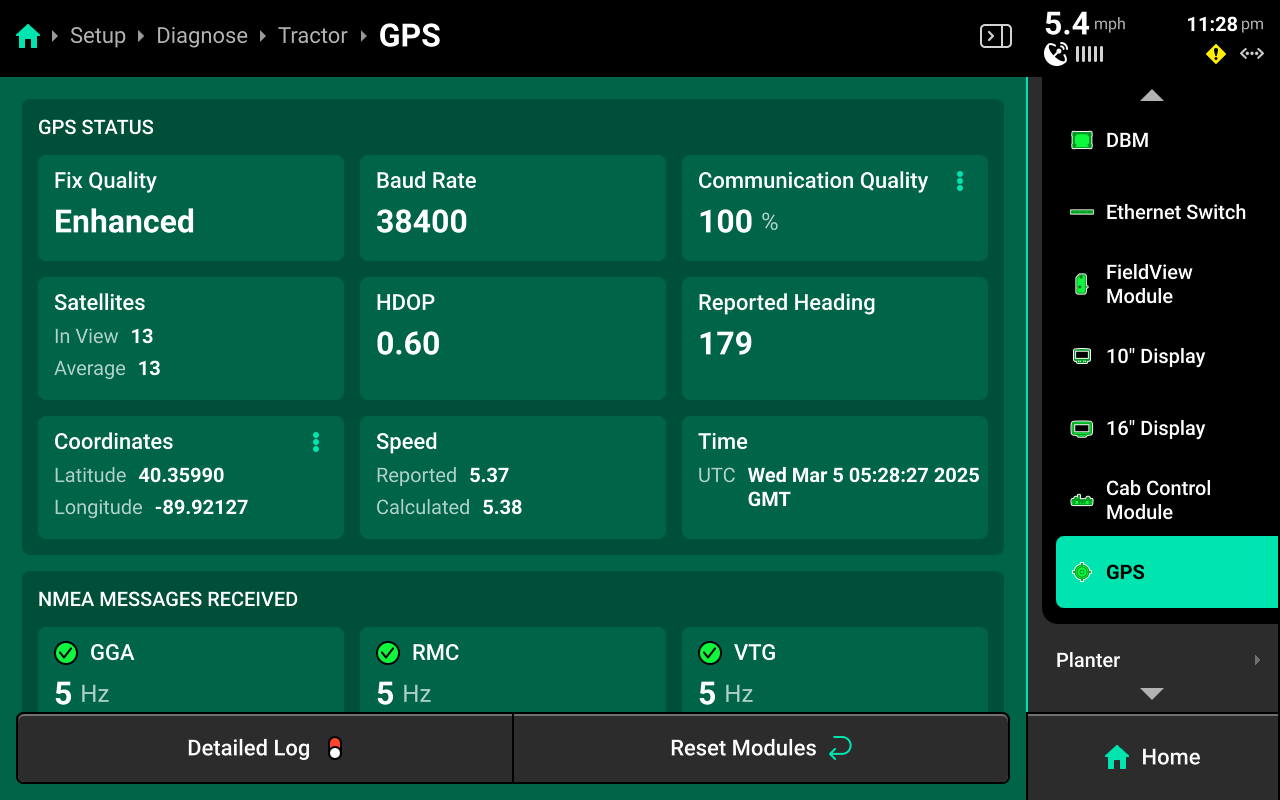
- Baud Rate : Measures communication speed between the GPS receiver and 20|20. A rate of 38400 is recommended for Precision Planting systems.
- Fix Quality : RTK is recommended for all Precision Planting control systems.
- Satellites in View / Average : An In View value lower than the Average value may result in reduced performance.
- HDOP : Horizontal Dilution Of Precision. Values exceeding 1 may result in lower performance.
- Reported / Calculated Speed : Difference between these values may cause control issues.
- NMEA Messages : Displays the rate per second that the GPS receiver is sending the required NMEA strings to the 20|20. All Precision Planting Systems require 5hz.
Precision Planting products require only GGA, RMC and VTG strings at 5hz. If the third-party receiver is configured to output a different set of NMEA strings or a different frequency, control issues and diagnostic information will be affected. Check for correct NMEA output (and other GPS diagnostics) whenever control issues occur or information does not display correctly on the diagnose screen.
Speed diagnostics are also displayed on this screen. Scroll on the center to view Radar speed / state and primary speed settings.
Implement
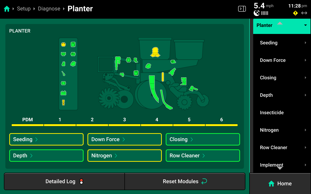
The Implement section of the diagnose menu will share the same name as the Implement profile that is selected in Equipment. A graphic of the implement and all devices / modules that are installed on it will be displayed.
Navigate to the desired system by pressing it in the center or the Navigation Menu.
Systems
A list of all hardware devices configured on the selected system will be displayed under the graphic in the center and in the Navigation Menu.
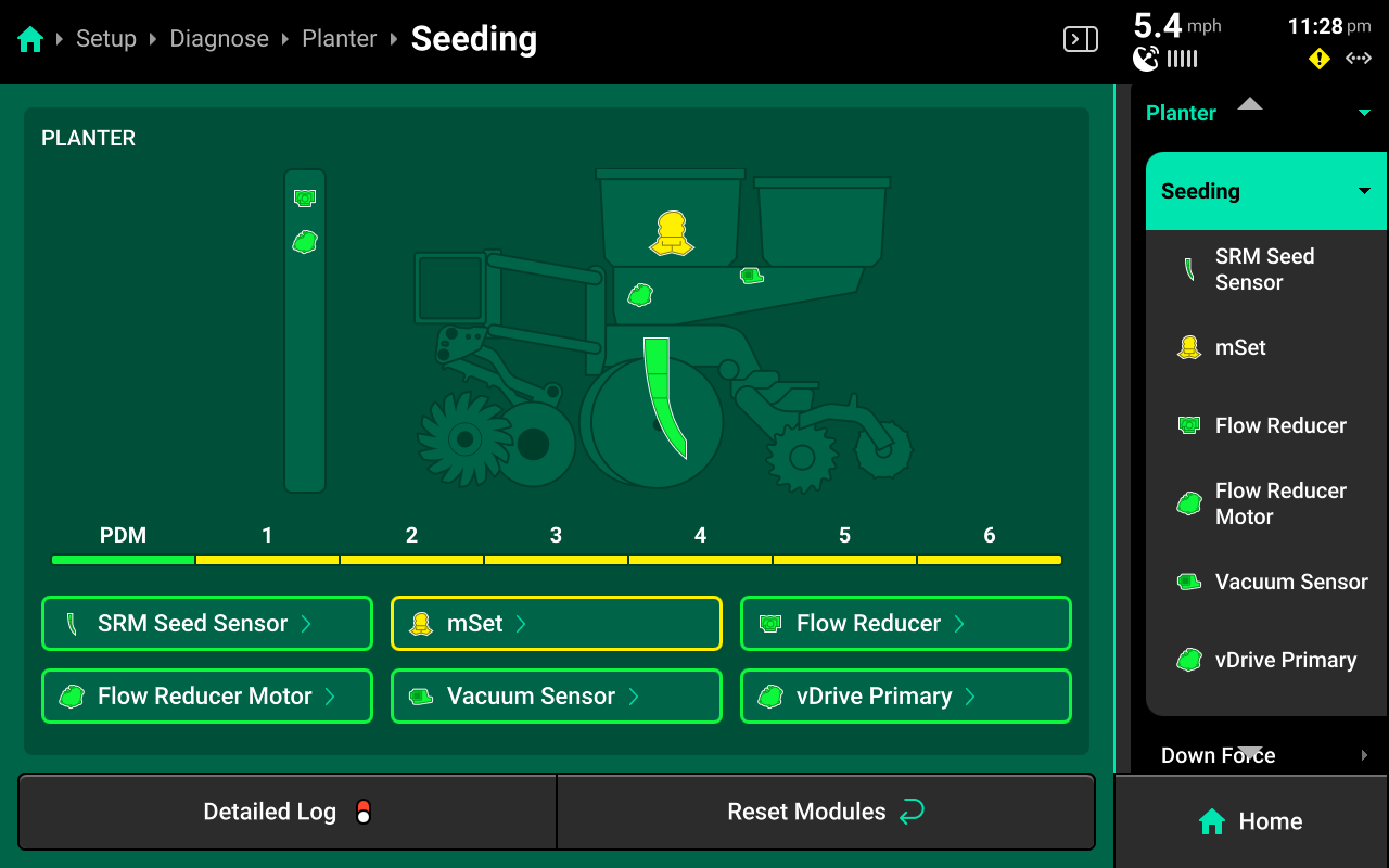
Press on the desired device to view a detailed diagnostic chart for that device.
Standard Hardware Diagnostics
A chart showing device health row-by-row for the selected hardware device will be displayed.
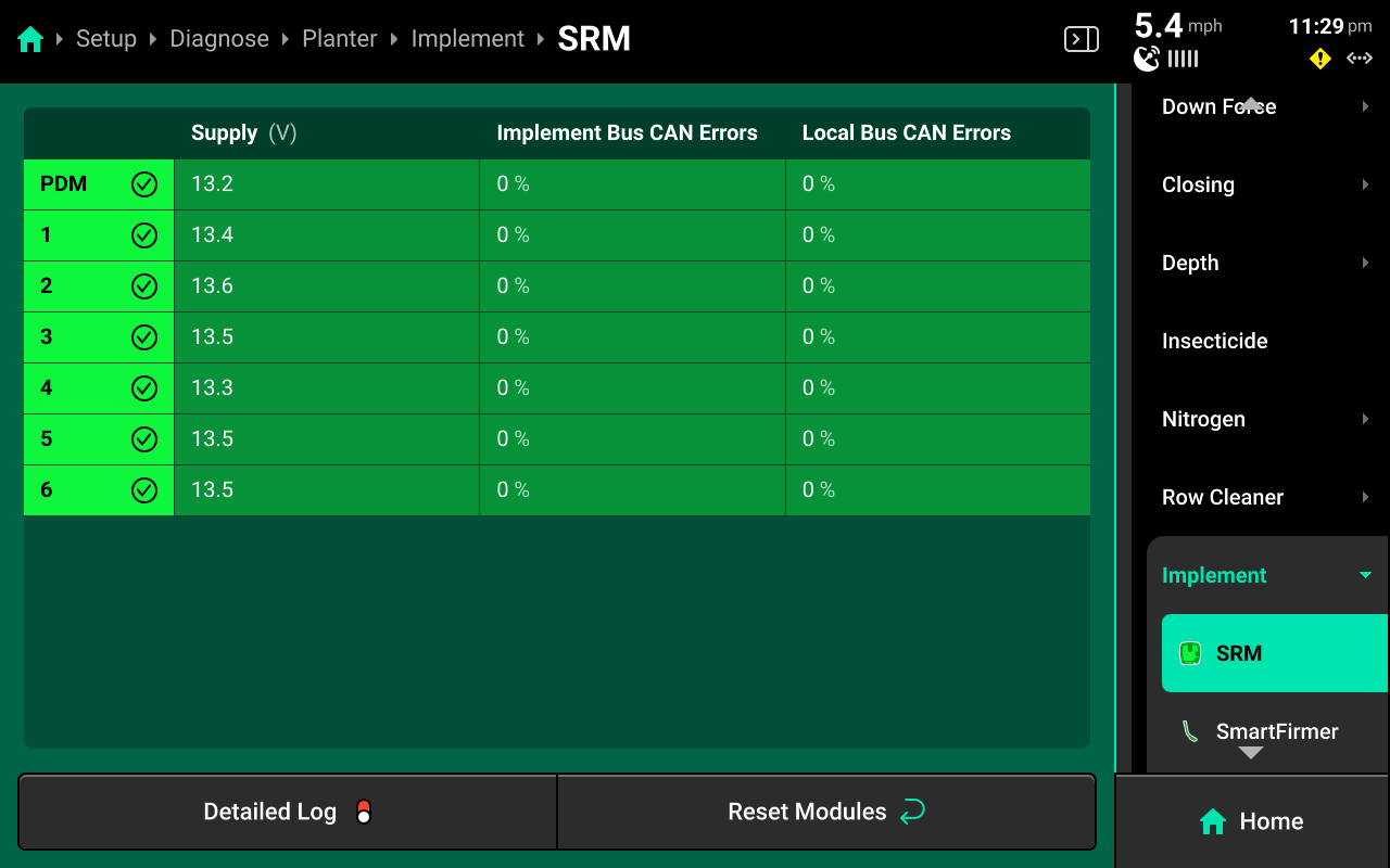
- SRM : View supply volts and implement / local (row) CAN errors.
- Ride Quality Sensor : View Good Ride readings from SRM accelerometers.
- Gyro / Implement Motion Sensor : View turn rate and acceleration readings.
- Lift Switch : View switch position and calibrated lift / lowered status.
SRM diagnostic details are accessible from Implement (Default) System on the Diagnose menu.
Refer to the appropriate system-specific operator's guides for diagnostic information on all other hardware devices.
Connectivity
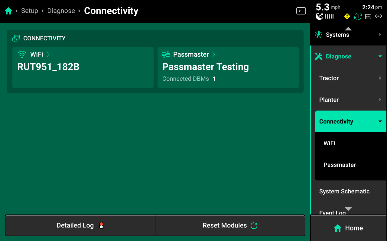
The Connectivity section of the Diagnose menu displays Wi-Fi and Passmaster connection status. Press on either option in the center or Navigation Menu to view each connection details.
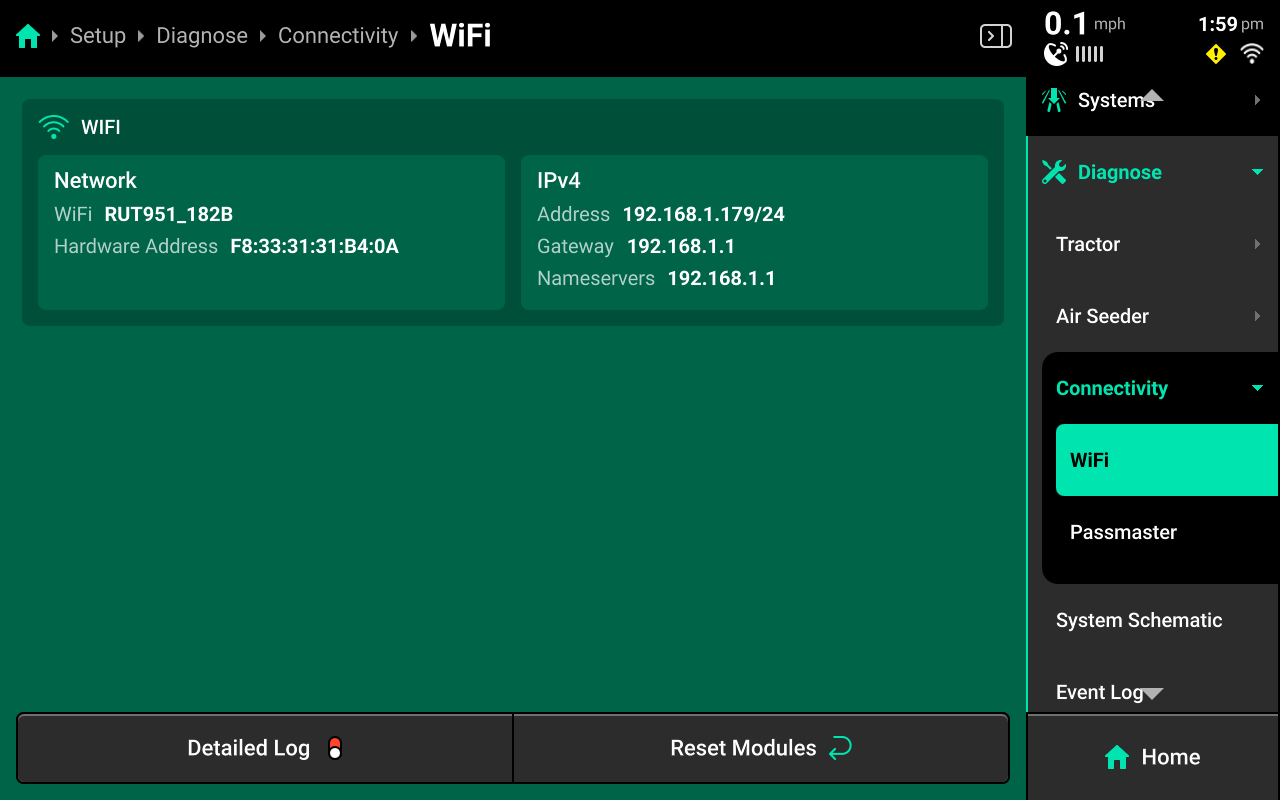
Wi-Fi
Displays network name and hardware MAC address.
Passmaster
Displays connected Panorama operation name and connected server, as well as DBM serial number / name and active field name. When multiple DBMs are connected to a Panorama operation, each DBM and information regarding its active field will be displayed below Connected DBMs.
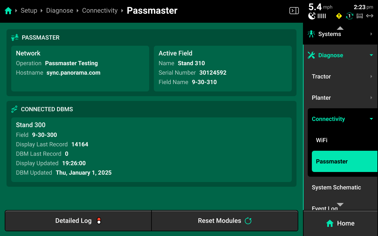
Name of Connected DBM
- Field : Active Field on Connected DBM
- Display Last Record : Last record received from connected display
- DBM Last Record : (non-functional as of 2025.1.7)
- Display Updated : Timestamp of last record received from connected DBM
- DBM Updated : Date of last software update for connected DBM
The Display Last Record value will constantly increase while the connected DBM is in operation. If this number is static, there is an issue with the internet connection on the connected DBM(s). Disconnect from and reconnect to internet on the DBM(s) and / or restart the router(s) providing interent the DBM(s). If this number is increasing but maps are not building on the Home Screen, restart the DBM(s) and / or navigate to Setup > Settings > Delete Data and press Delete Local Cache Data. See Clearing Device Settings for more details.
System Schematic
The System Schematic displays a schematic overview of all Ethernet and CAN modules / devices connected to or configured in the 20|20. Use the System Schematic to identify setup issues and damaged modules / harnessing and determine troubleshooting procedures.
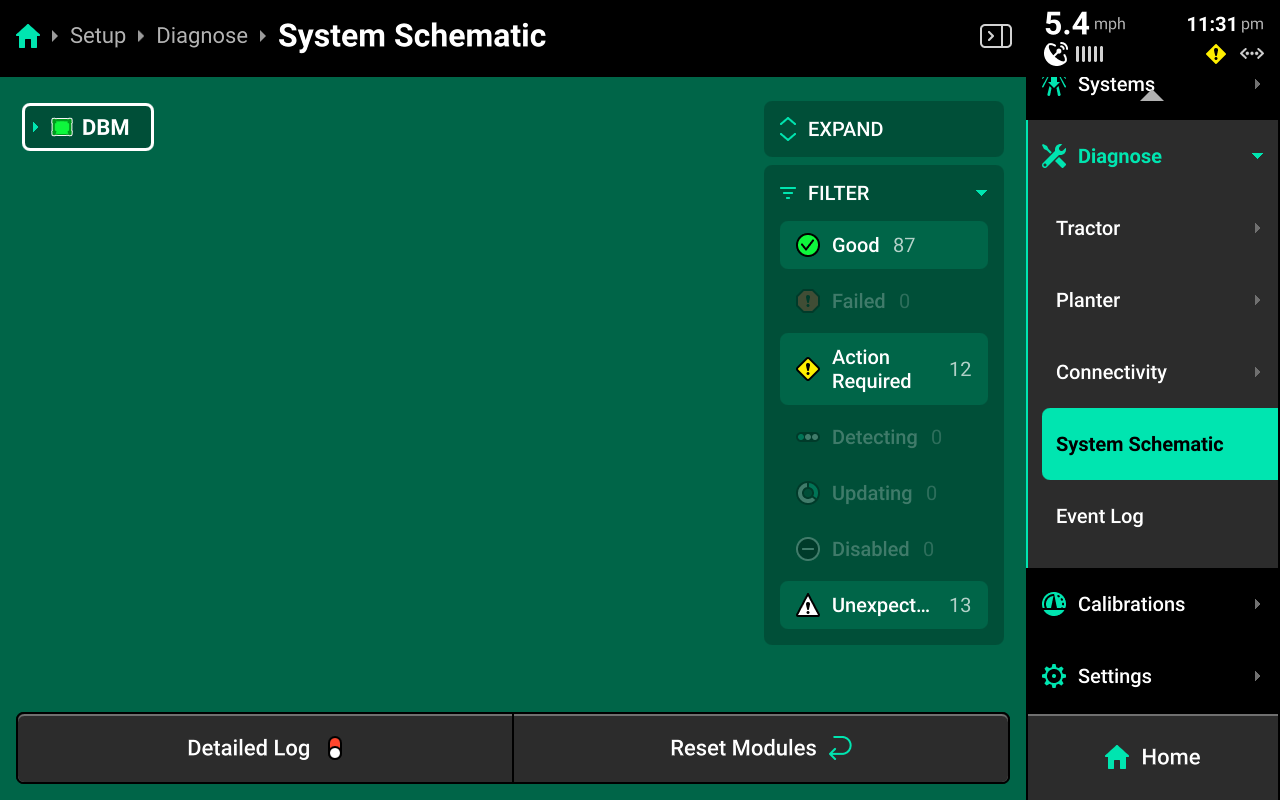
The icon to the left of each device name represents the health of that device. The outline around the device name indicates the health of the devices connected to it. If there are both red and white devices connected, the outline will be red.
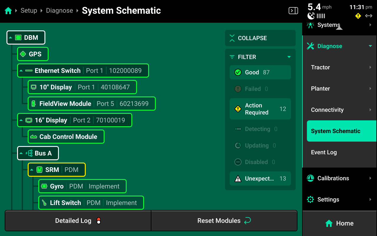
For any device that has a dropdown arrow next to its icon, press that arrow to expand the schematic to show all connected devices. Alternatively, press Expand in the upper right corner to immediately expand the entire schematic.
Press the filters on the right side to filter all modules by health. Any filter which is active will have a blue-green outline. Press any active filer to deactivate it.
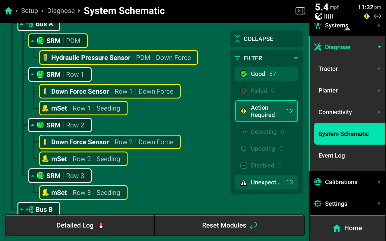
Using the Schematic
Use the following tips when diagnosing system issues using the system schematic.
-
Red devices typically indicate damaged / disconnected modules or harnessing.
-
White devices typically indicate incomplete system configuration.
-
An incorrect number of CAN bus devices (e.g. SRM) with some displayed in green, white and / or red typically indicates incorrect Module setup.
-
Yellow devices typically indicate that a device is uncalibrated, underpowered, or commanding / being commanded outside accepted parameters.
-
It is possible to use a second display connected to the DBM to view the system schematic while performing setup on the primary display to streamline the setup process.
Event Log
The Event Log contains a list of notifications that the 20|20 has generated for the user. Use the search filter at the top to search events by name.
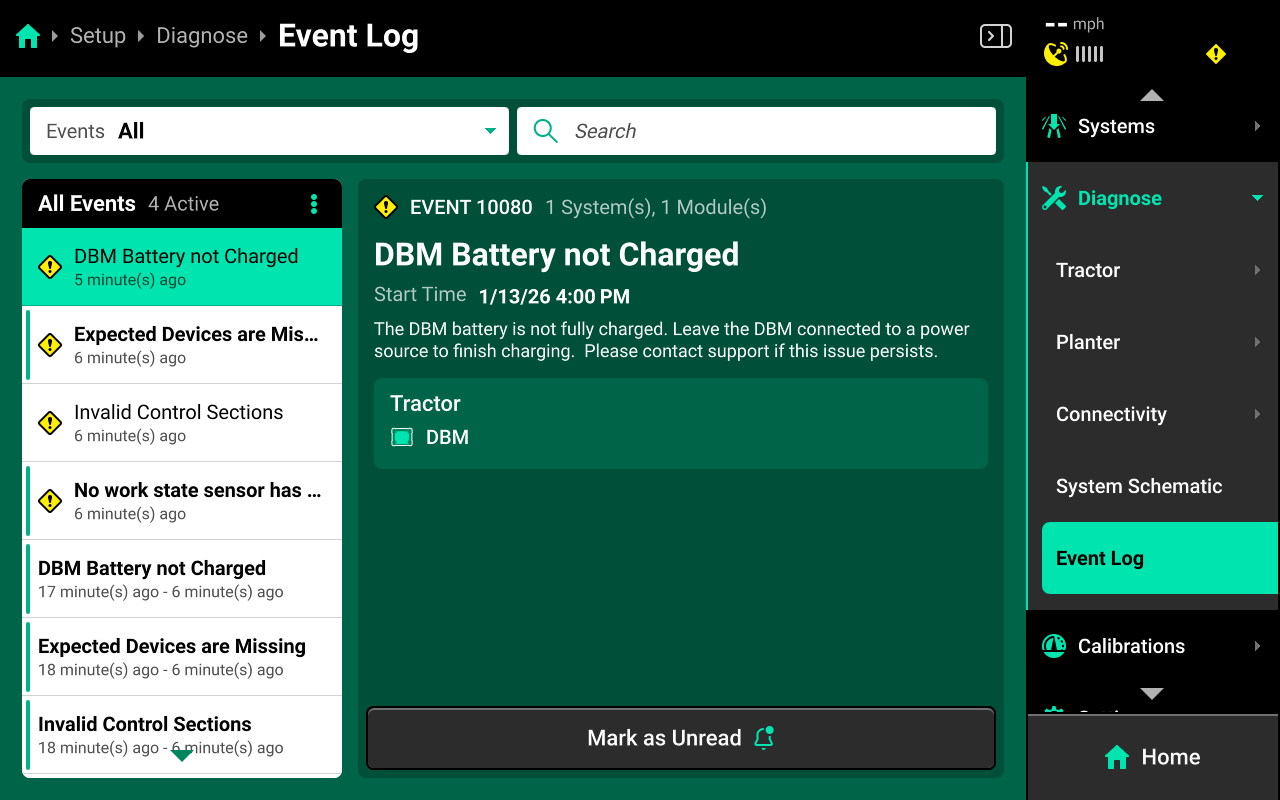
Typical events include, but are not limited to:
- Uncalibrated devices : Any device which is not calibrated, but must be in order to function.
- Misconfigured devices : Any device which was configured improperly.
- Damaged devices : Damage is detected on connected devices (e.g. internal DBM battery).
- Missing devices : Devices were set up, but not detected.
- Incompatible setup : Incompatible devices (e.g. wrong load cells for the row unit selection) or an unusable system setup was configured.
 Calibrations
The Calibrations menu is used during first time setup to prepare all systems for proper functionality, to recalibrate hardware at season start, after installing new hardware devices, and when changing products or zeroing sensors. Hardware which requires calibration to function properly will be displayed in yellow on the Diagnose menu until they have been calibrated.
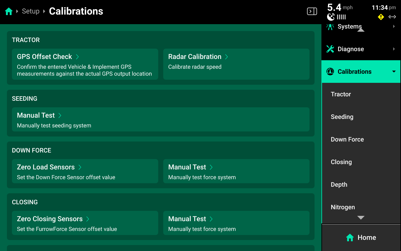
A master list of available calibrations will be displayed on the Calibrations Landing Screen. Filter this list by pressing on the options displayed below Calibrations in the Navigation Menu.
This guide will detail calibrations common to all Cab / Implement combinations. Refer to system-specific operator's guides for information on running other system calibrations.
Sensors such as load cells and EM FlowSense are not zeroed on the diagnose screen. Use Calibrations to zero sensors.
Cab Calibrations
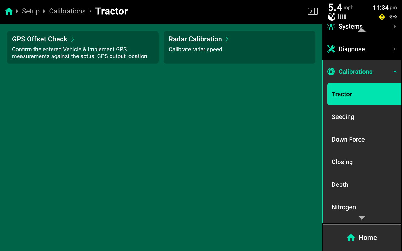
Press (Cab Name) in the Navigation Menu to perform a GPS offset check or calibrate radar.
GPS Offset Check
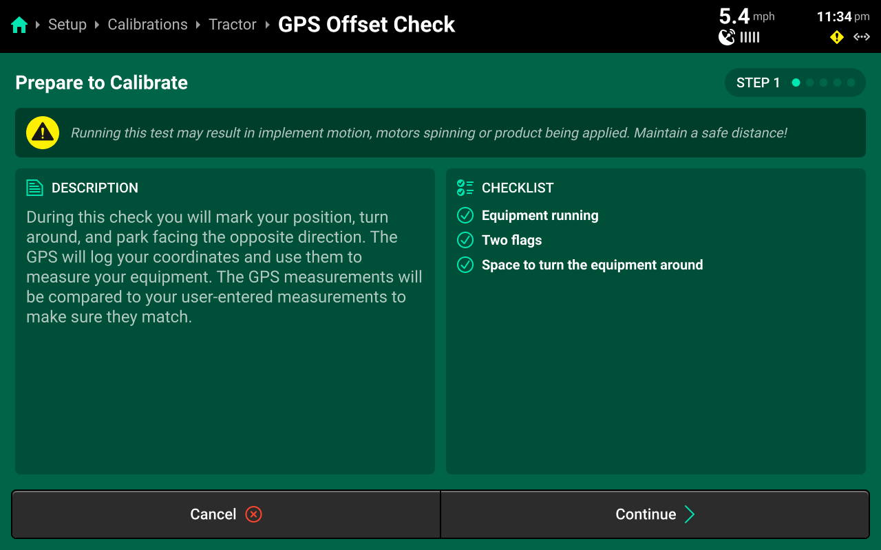
Run through the calibration wizard to perform the offset check following the on-screen instructions. Ensure that the application points / seed exits are even with the placed markers on step 1 and step 4.
This test may be easier to perform with a spotter to determine that the application points / seed exits are even with the placed markers.
Resulting differences of less than 12 inches are recommended, but best control will be experienced with differences as close to 0 as possible. Higher differences will result in less accurate swath timing.
Precision Planting Product Support recommends to repeat this test and / or remeasure implement dimensions to achieve more accurate results before using start / stop timings and application offsets to fine-tune control. Support also recommends to perform this check at every season start.
Radar Calibration
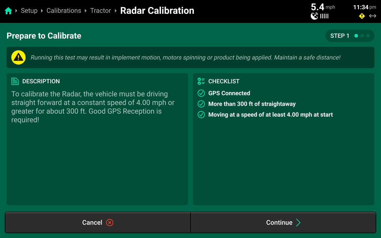
Run through the calibration wizard to set pulses / foot for the radar. Good GPS signal is required. Once the bar fills, the calibration is complete. Navigate to Setup > Diagnose > (Cab name) > GPS and scroll on the center screen to confirm that GPS and Radar speed match. Perform the calibration again if necessary.
Implement Calibrations
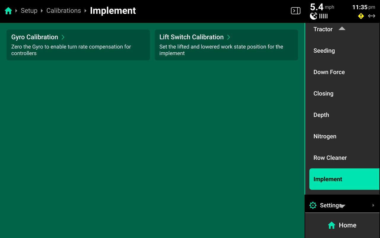
Press the (Default system name) system to calibrate the Gyro / IMS or calibrate a height sensor.
Gyro / IMS Calibration
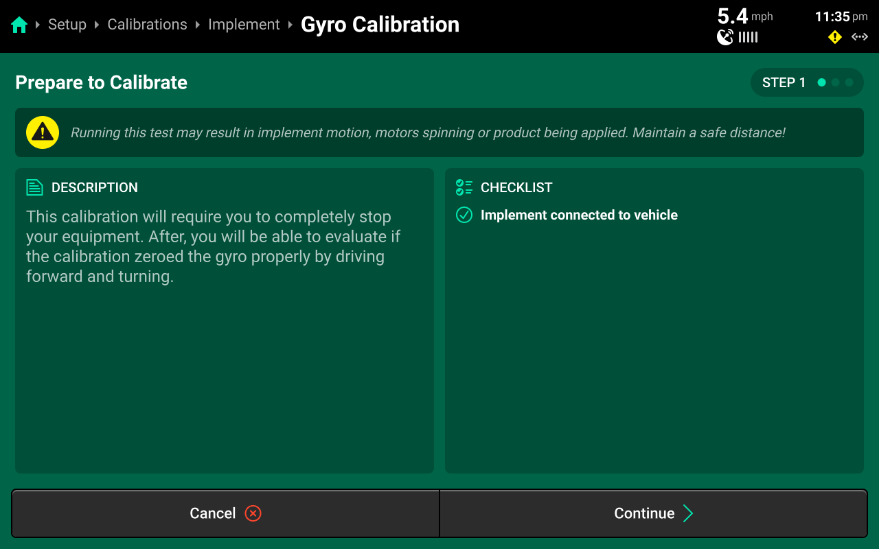
Run the calibration wizard to zero the gyro or IMS. Follow the on-screen instructions to zero the sensor when necessary.
Lift Switch Calibration
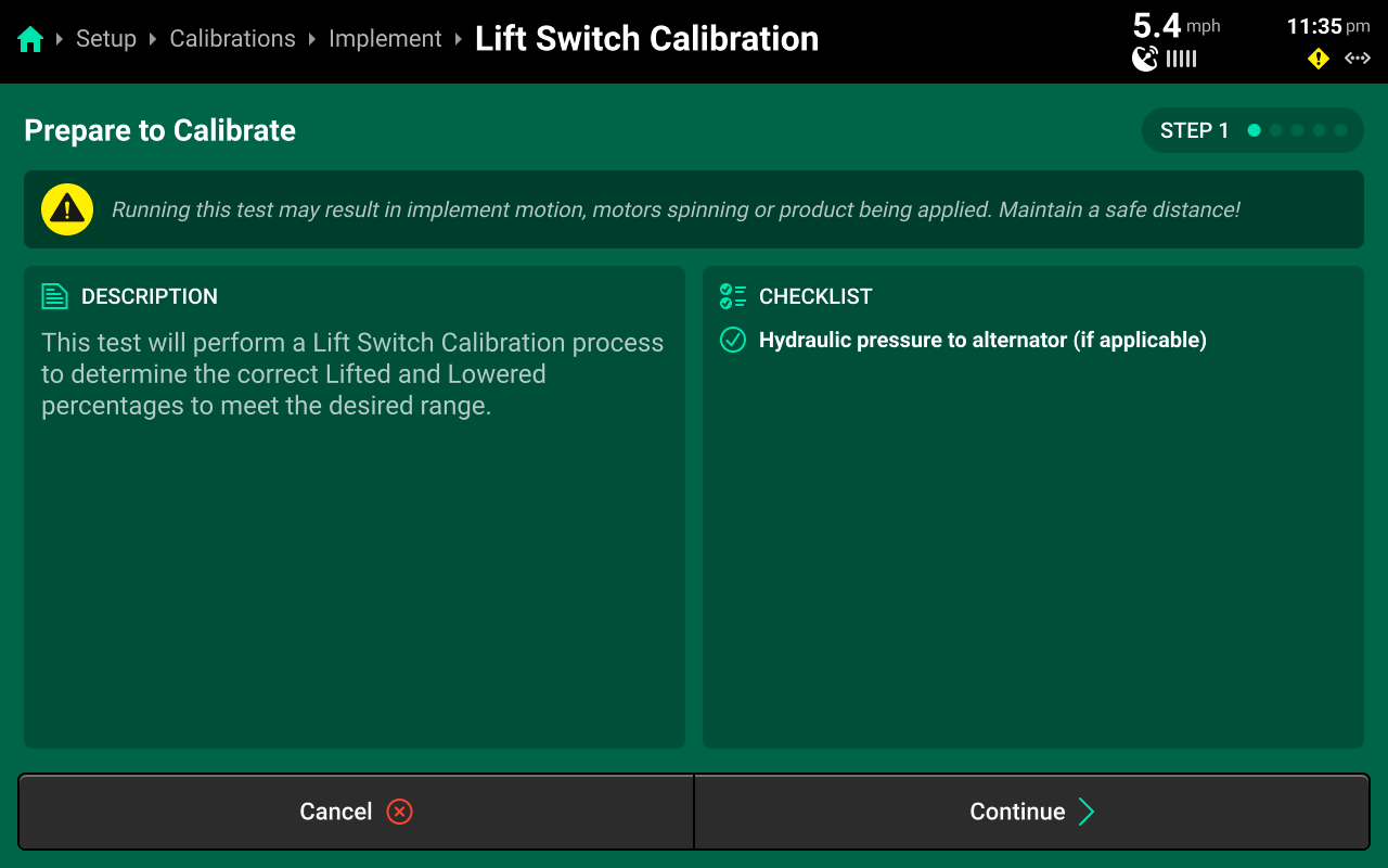
Run the calibration wizard to perform a three-point calibration of a lift switch. Set Raised, Lowered and Engagement height on the different steps.
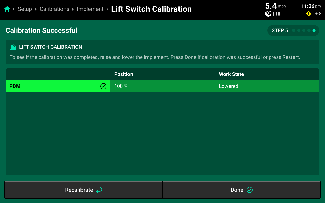
Use step 5 to raise / lower the implement and confirm correct position readings.
 Settings
The Settings menu is used to import / export / delete 20|20 data, connect to Wi-Fi or Panorama, and adjust user preferences.
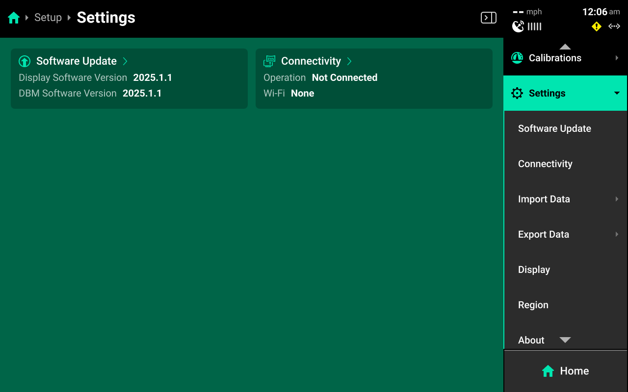
The Settings Landing Screen displays basic system information such as software version and active connections.
Software Update
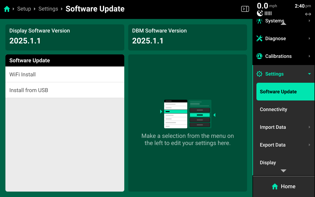
Use the Software Update screen to update via Internet or external USB drive.
Select either option in the left window to perform either update process.
Wi-Fi Update
Precision Planting hosts commercial release software updates online free of charge. Connect the 20|20 to the Internet and select the desired software version in the right window to download and install the update. The 20|20 will restart after downloading to finish the update.
USB Update
The most recent versions of commercial and limited release software may be downloaded from 2020.ag and placed on the root drive of an external USB drive. The software update file must not be placed into a folder on the USB drive. Connect the USB drive to the USB port on the display. Press Install from USB and select the software update from the popup to perform the update.
In some cases, software updates may fail. In these cases, it is often necessary to try the update using a different, higher quality USB drive. Many older or lower quality USB drives have weak internal soldering and inferior components which may cause update issues.
Boot Software
In rare occurrences, software mismatches between display / DBM, device crashes, or other update issues may occur. In these cases, it is often necessary to use the boot software process.
Precision Planting Product Support recommends the following process to increase success rate for boot software.
- Download the desired version of boot software by visiting 2020.ag and clicking either commercial or limited release. Then scroll to the bottom of the page and click View complete list of changes by release. Download the desired boot software version from the list and place it onto a USB drive using the same instructions as standard software. Ensure that the file does not have spaces or parentheses in the file name.
The 20|20 cannot boot to the version of software that is currently installed. For example, if 2025.0.0 was the last installed version, download 2024.0.2 boot software
-
Unplug the display and implement from the DBM and press the power button on the back of the DBM. Wait until the DBM LED goes out.
-
Connect the USB drive to the USB port on the DBM. Then press the power button on the DBM to turn it on.
-
Wait for the following light sequence to complete.
| LED | Description |
|---|---|
| Solid White | Powering on |
| Solid Yellow | Initializing |
| Flashing Yellow | Reading boot software |
| Solid Yellow | Initializing |
| Flashing yellow | Software Update in Process |
| Solid Yellow | Post update Finalizing |
| Solid Blue | Fully updated to 25.0.x or older software |
| -or- | |
| Solid Green | Fully updated to 25.1.x or newer software |
-
Disconnect the USB drive from the DBM.
-
Connect the USB drive to the USB port on the Display. Then connect the display to the DBM.
-
The display will go through a boot up sequence as it reads the boot software and eventually load the Home screen. Then remove the USB drive from the display and resume normal operation.
An FVM may also be updated using boot software in troubleshooting cases. Disconnect the FVM from the DBM and iPad, then wait for the FVM LED to go out. Connect the USB drive with boot software loaded to the USB port on the FVM, then reconnect the FVM to the DBM and wait for the FVM light to go purple.
Advanced Users
Boot software is the same file as a standard software update file. Only the file name is different. Any software update file may be renamed to:
2020Gen3-full
This will "convert" the standard update file to boot software.
Connectivity
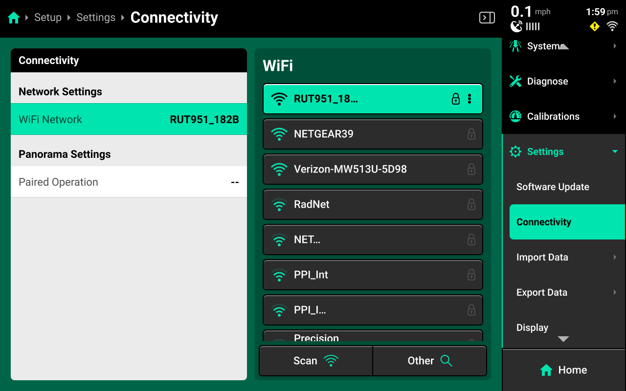
Use the Connectivity screen to connect to Wi-Fi or pair the 20|20 with a Panorama operation.
Connecting to Wi-Fi
Press WiFi network in the right window and select the desired network in the left window. Enter the network password using the popup keyboard. Press Scan to refresh the list of available networks. Press Other to manually enter network name. Press Forget on a saved network to disconnect and forget password.
For security reasons, the 20|20 will only connect to a password-protected Wi-Fi network.
If the 20|20 will not connect to the desired network, try to connect to another network (e.g. a phone hotspot) for testing purposes to determine if the issue is with the network, or with the interior hardware of the 20|20.
Connecting to Hardwired Internet
A hardwired internet connection will typically be the most reliable and fastest source of Internet connection.
To connect the DBM directly to an Internet access point, connect a third-party USB-A to Ethernet adapter to the USB port on the DBM. Then connect the adapter to the Internet access point using an Ethernet cable. Do not connect the Internet access point to the DBM using the POE ports.
Pairing with a Panorama Operation
Select Paired Operation in the left window and press Pair Device to run the pairing wizard.
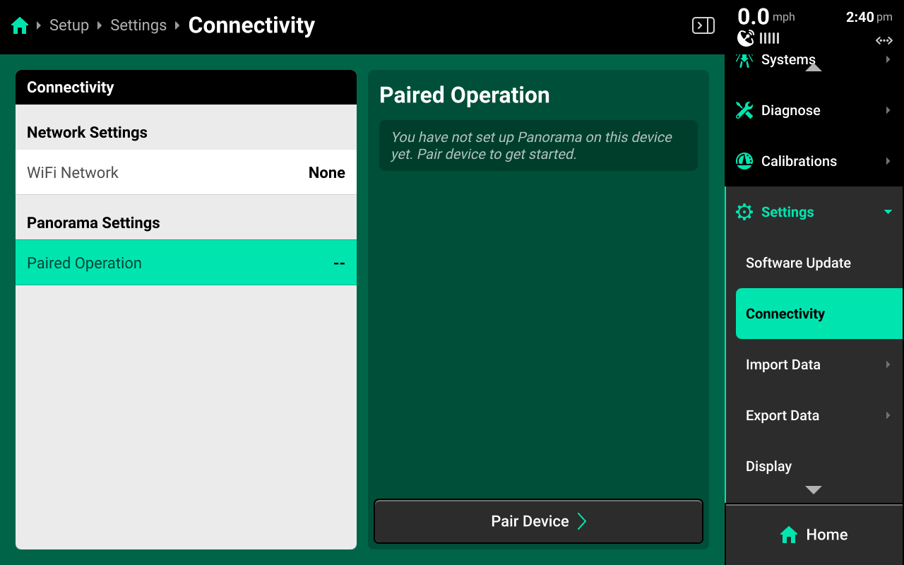
Ensure that step 1 displays a Hostname in the bottom right. If it does not, the 20|20 is not connected to Internet or Panorama servers are inoperable. Then press Continue.
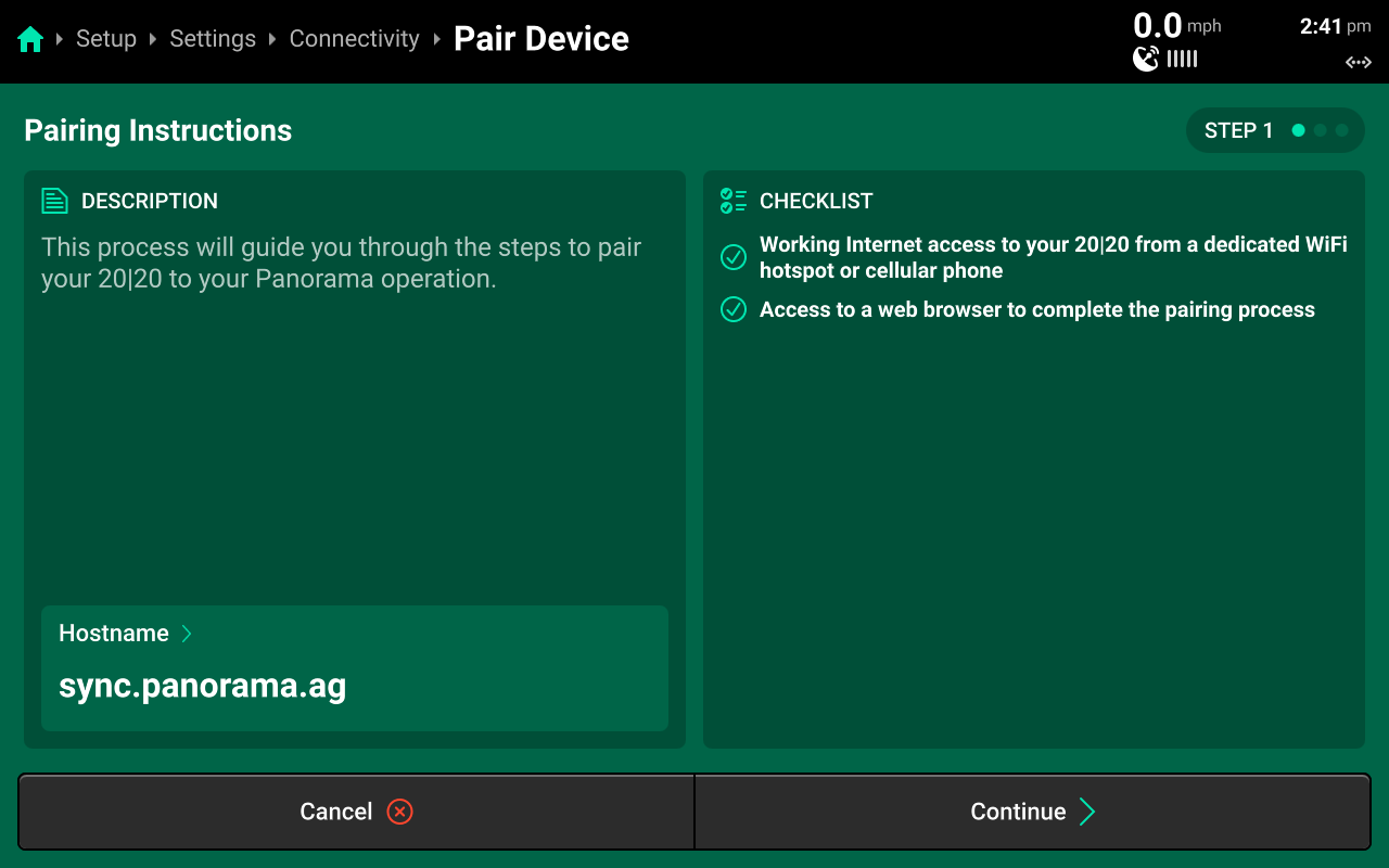
A pairing code and QR code will be generated. Scan the QR code in the Panorama app, or enter the pairing code on the Panorama website by clicking Add Device + on the Devices tab under Manage Operation.
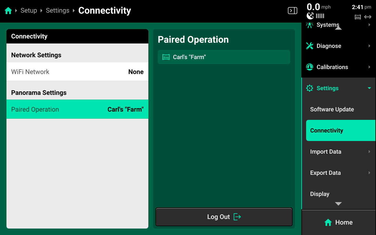
Import Data
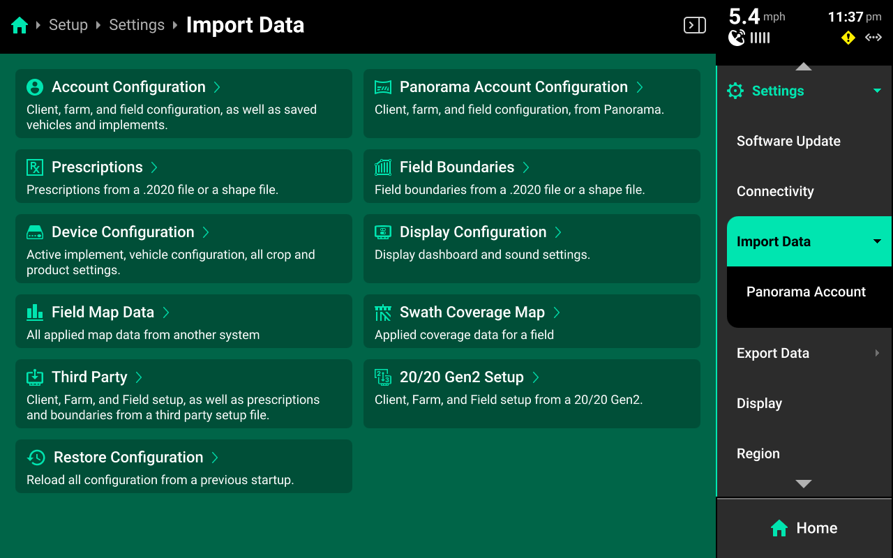
Use the Import Data screen to import different types of data from an external USB drive or Panorama into the 20|20 or to restore configuration using an internal backup.
Configurations, Maps, and other monitor data
For configurations, maps, and third-party or 20/20 Gen 2 data; connect an external USB drive with the desired files loaded and press the desired option. A popup with all files of that type which are loaded on the USB drive will open. Select the desired files to import them.
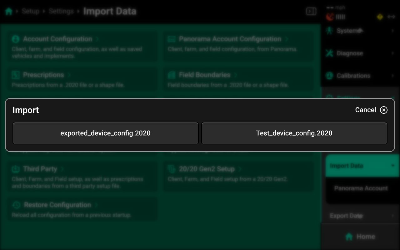
Importing Device and Display Configurations will replace the active configuration. Any unsaved changes will be lost. Save and / or export the active Device or Display configurations before importing.
Importing an Account Configuration will erase all saved Equipment profiles, display layouts, Clients / Farms / Fields, and field map data. Export all desired elements before importing.
Prescriptions and Boundaries
For prescriptions and boundaries, connect an external USB drive with the desired files and select the desired option. A popup with files of that type which are loaded onto the USB drive will open. Select each of the desired files, or press Select All in the lower right, then press Import.
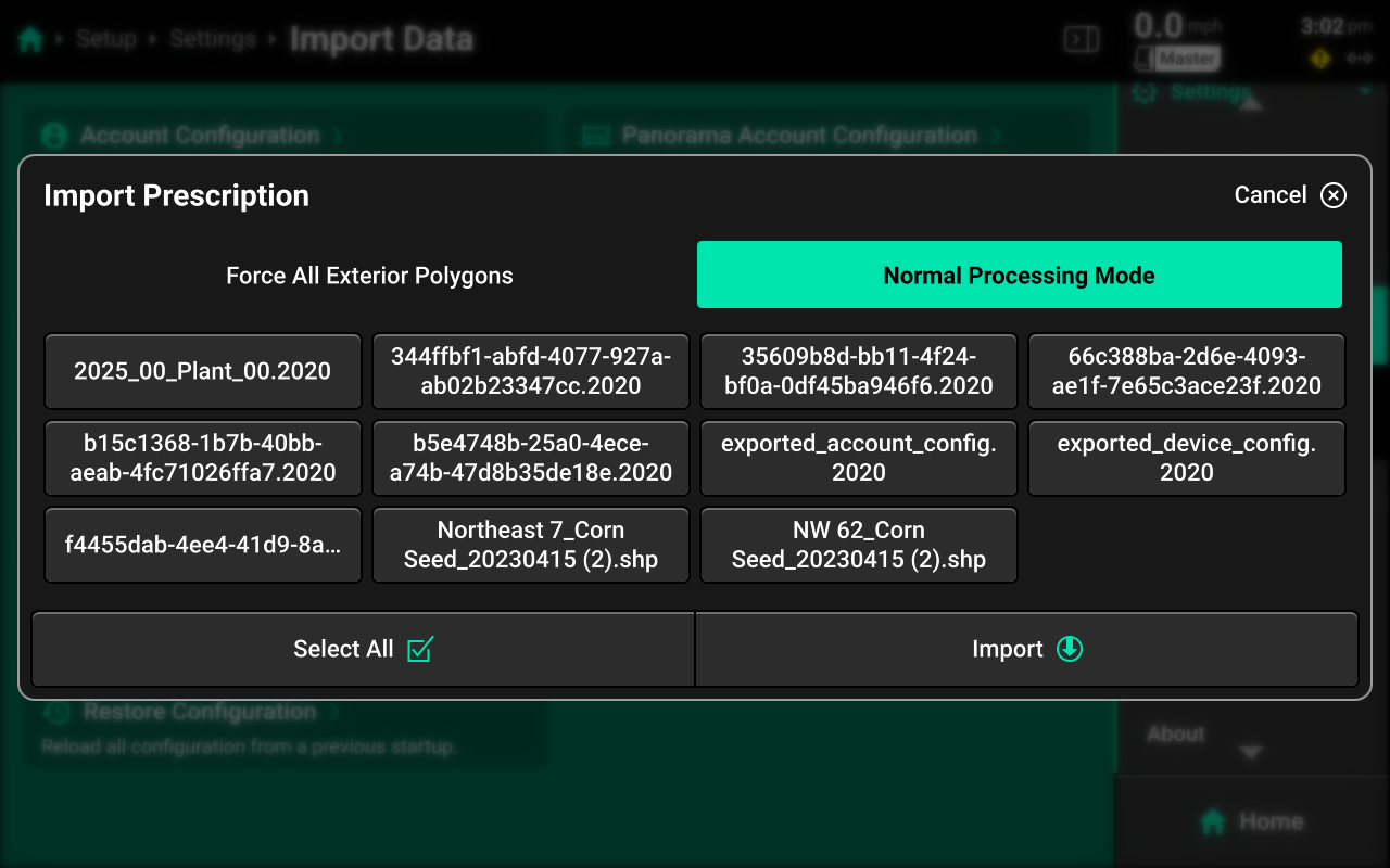
The Force All Exterior Polygons option is a troubleshooting measure intended for use when experiencing improper prescription / boundary control. Delete the originally imported file before using this option.
All prescriptions and boundaries must be in shape file format (or .2020 file format) to import into the 20|20. A shape file consists of 3 files with the same name but a different file extension (.shp + .shx + .dbf). For example, to import a prescription named "Seeding", the user must to generate the following files from a third-party program:
- Seeding.shp
- Seeding.shx
- Seeding.dbf
The user must then place those 3 files onto a USB drive, then import into the 20|20. The 3 files will show as 1 file in the popup.
If issues are encountered when importing prescriptions or boundaries, try using a different USB drive, or try importing only one shape file at a time.
Panorama Account Configuration
Press Panorama Account Configuration or select Panorama Account under Import Data in the Navigation Menu to import a Client / Farm / Field structure from a paired Panorama operation.
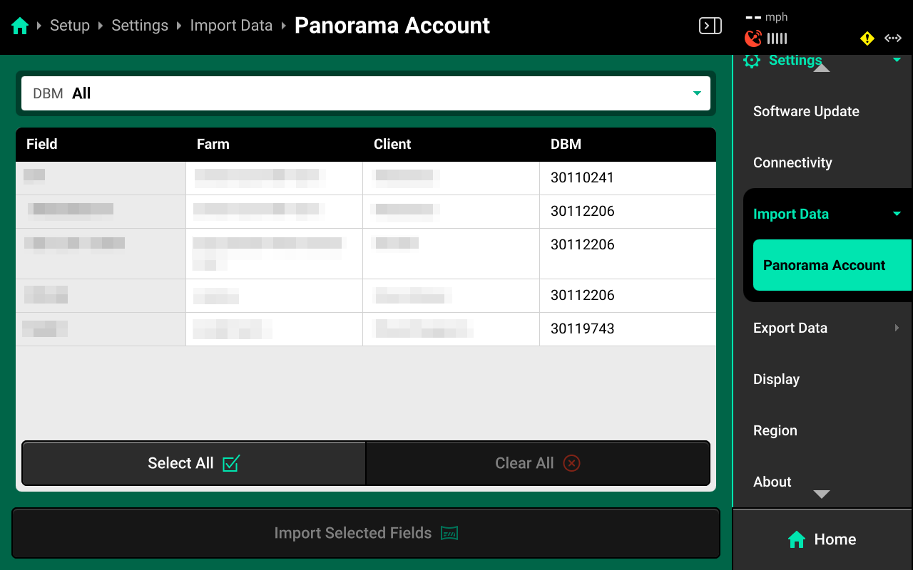
The table in the center displays all fields and their associated Client and Farm, and the DBM which they were created on. This table may be filtered by DBM using the dropdown box at the top.
Restore Configuration
Press Restore Configuration to open a popup database of backup device configurations. The 20|20 will generate a backup of the active Equipment profile every time it is power cycled if there is not an existing backup in the last 24 hours. Select an entry from the database to load it.
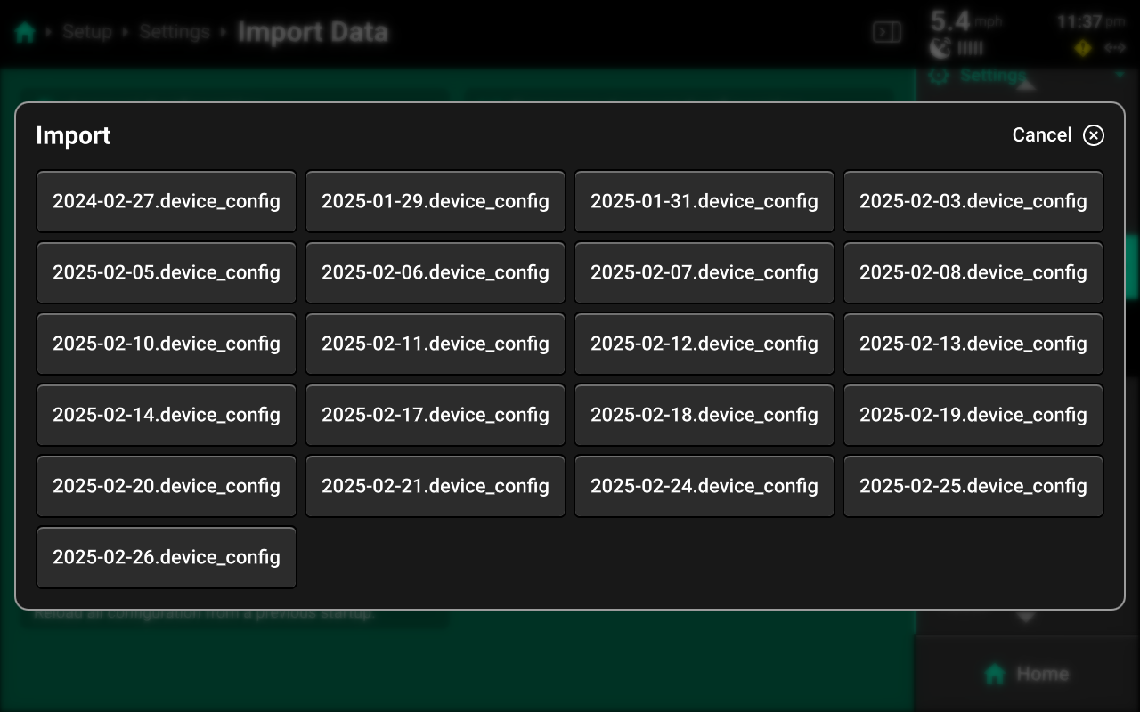
Using Restore Configuration will replace the active configuration. Any unsaved changes will be lost. If desired, save and / or export the active Device and Display configurations before importing.
Export Data
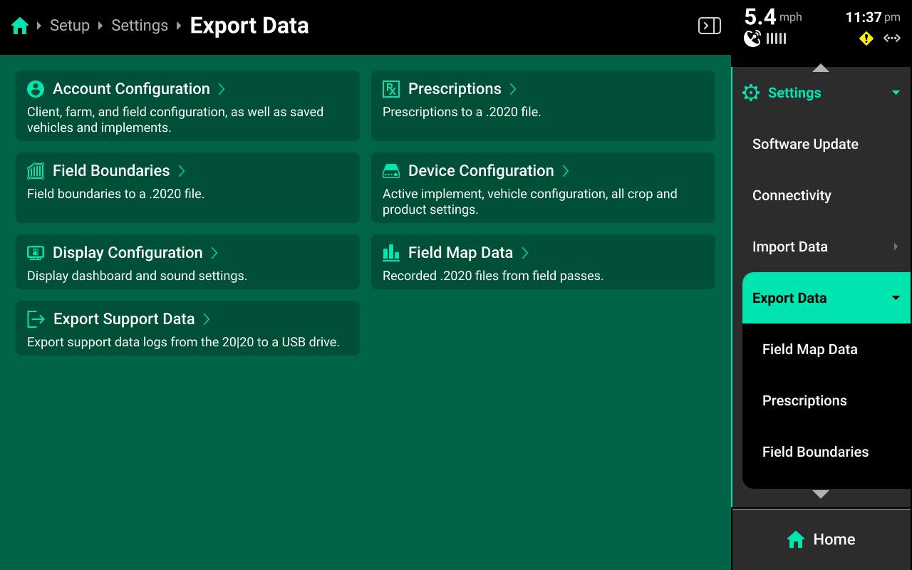
Use the Export Data screen to export different types of data to an external USB drive or to Panorama.
Account / Device / Display Configurations
Connect a USB drive, then press the desired option and use the popup keyboard to enter the desired name for the configuration. Press enter on the keyboard to export the configuration with the entered name.
Prescriptions / Boundaries
Connect a USB drive, then press the desired option in the center or under Export Data in the Navigation Menu to open a table which displays all files of the selected type saved on the 20|20.
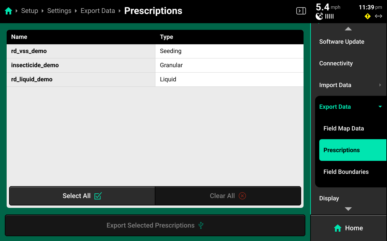
Press each desired file in the table or press Select All in the bottom right, then press Export Selected (File Type) to export all selected files to the USB drive.
Field Map Data
Press Field Map Data in the center or under Export Data in the Navigation Menu to open a table which displays all field map data files.
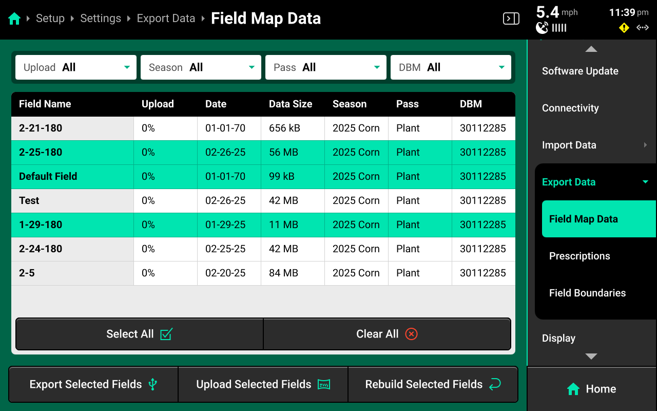
Press each desired file in the table or press Select All in the bottom left. Press Export Selected Fields to export all selected files to a connected USB drive.
To export to Panorama instead of a USB drive, press Upload Selected Fields in the bottom center to export all selected files to a paired Panorama operation. Internet connection is required for Panorama upload.
To rebuild FVM fields, press Rebuild Selected Fields in the bottom right.
If exported files display on a desktop / laptop computer as .tmp files, then the export did not complete. Typically, this is due to a USB drive that is too small or low quality. Try exporting only one file, or try a higher quality USB drive.
Support Data
Connect a USB drive, then press Export Support Data to export data logs and all screenshots onto the USB drive. Typically, this will only be done in troubleshooting situations when requested by Precision Planting Product Support.
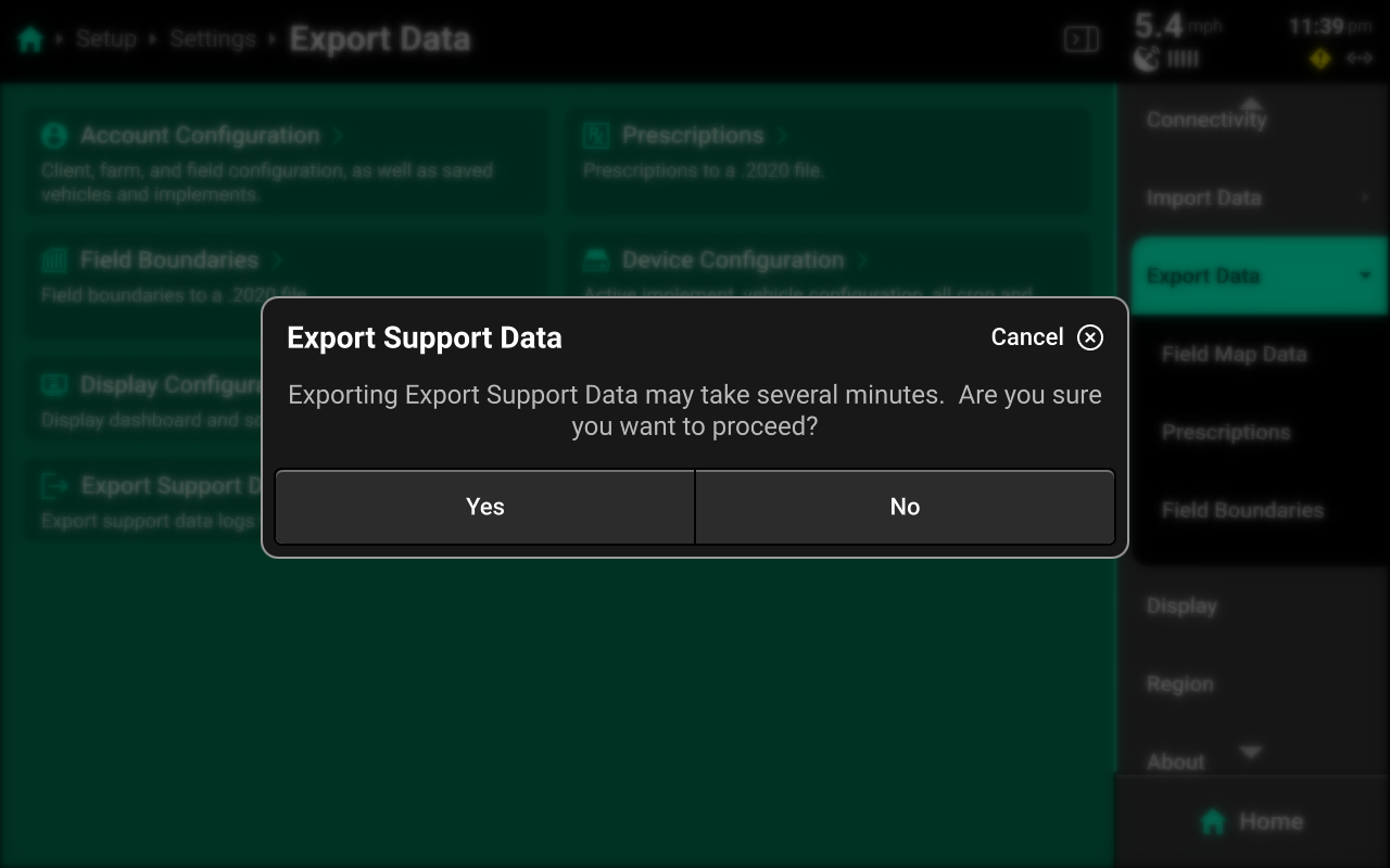
Display
Use the Display screen to adjust audio / visual settings, disable display alerts, or perform a touch screen test.
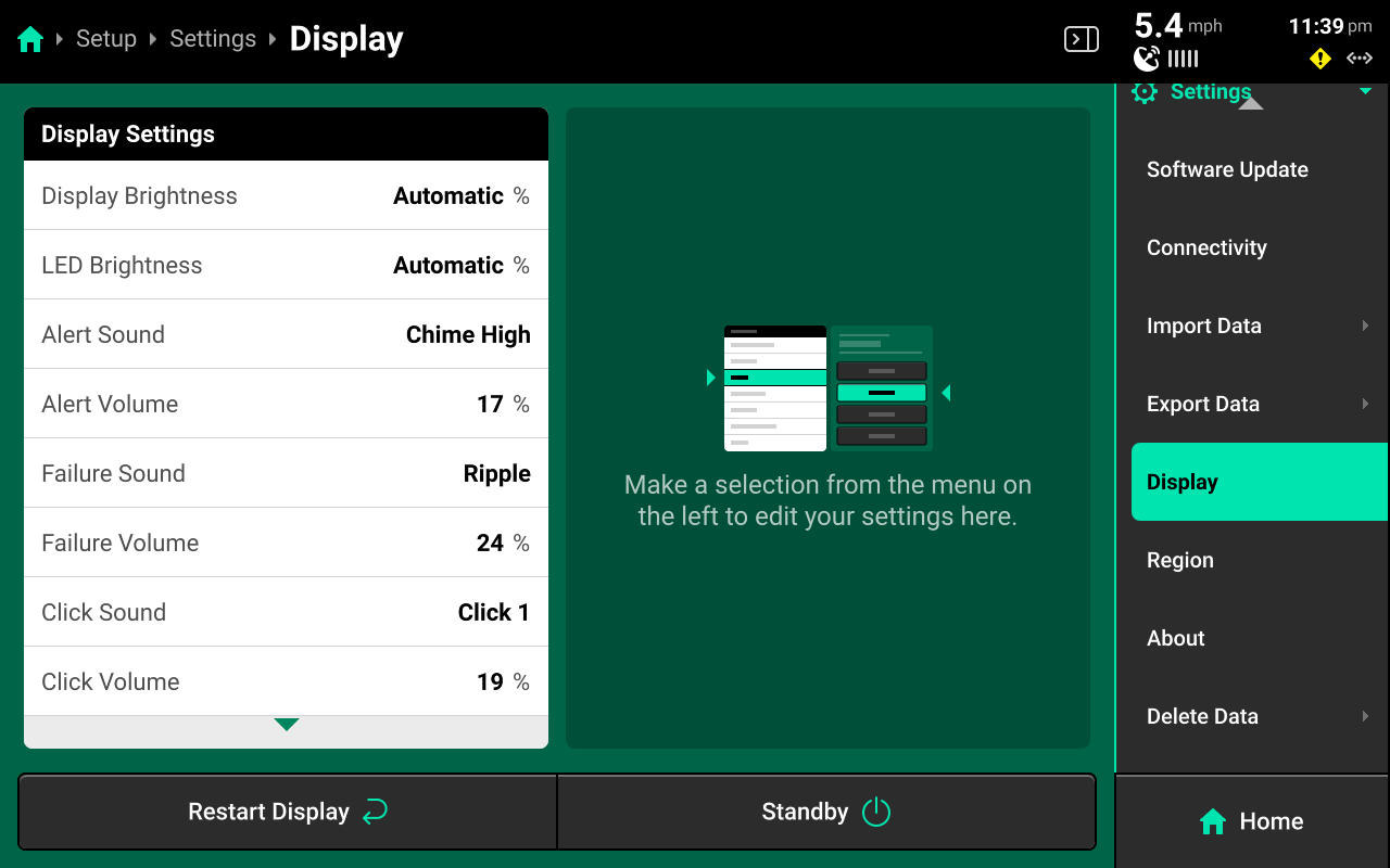
Press Restart Display in the bottom left to restart the display only. The DBM will not restart.
Press Standby in the bottom left to put the display into low power / sleep mode. The screen will stay dark until the user presses anywhere on it.
Brightness
Select Display or LED Brightness in the left window, then use the toggle in the right window to switch between automatic and manual brightness and the slider to increase / decrease manual brightness level. Automatic will utilize the photosensor on back of the display to dim or brighten the respective setting.
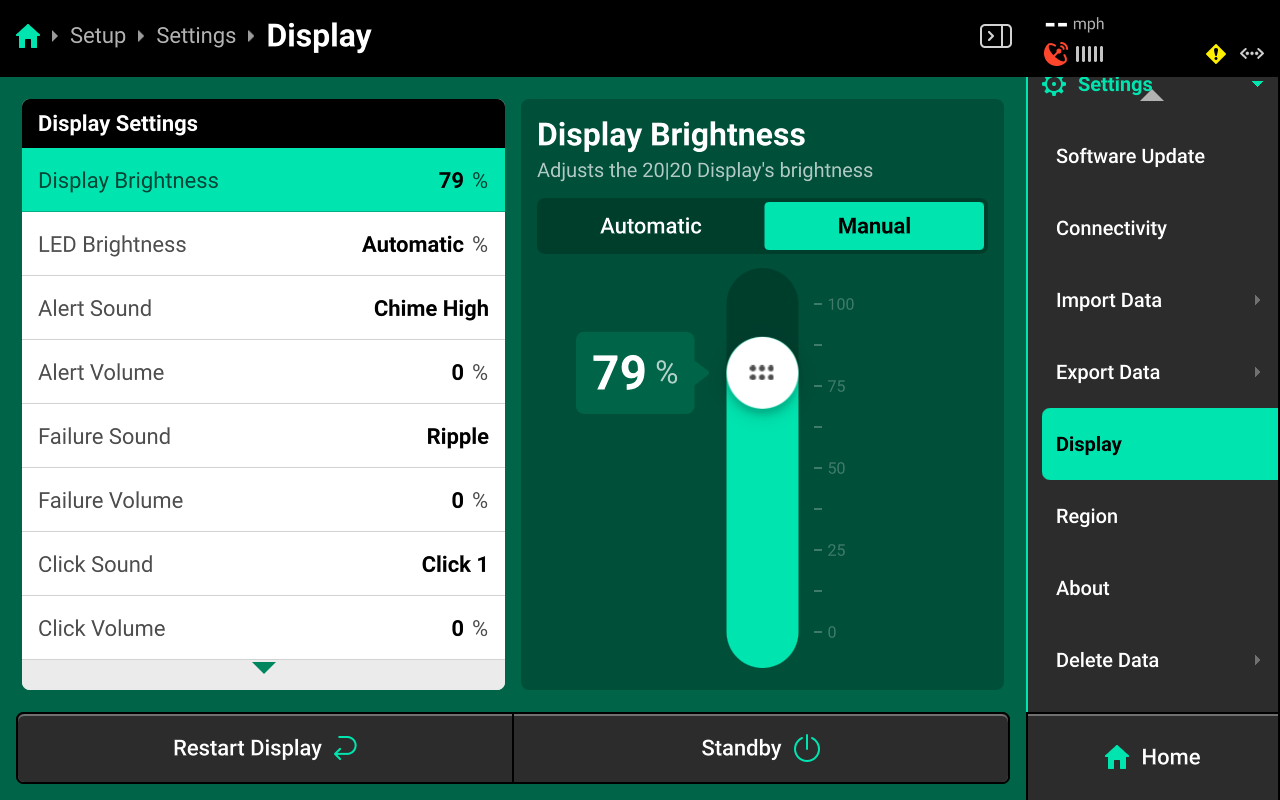
Sounds
Select a sound and / or volume in the left window, then select a sound for the setting or adjust its volume in the right window.
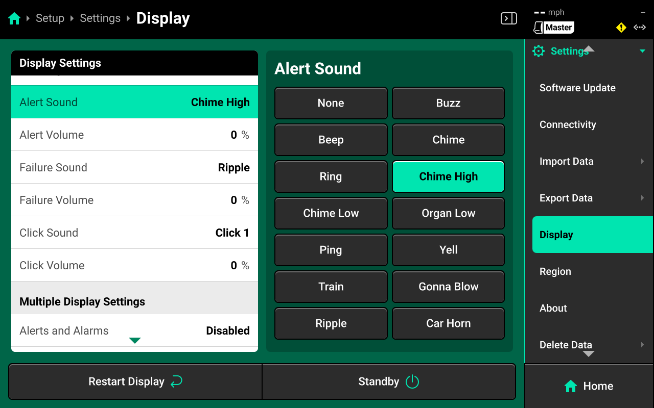
- Alert : Sound played when a user-defined system alert threshold is reached or a hardware device is functioning sub-optimally.
- Failure : Sound played when a user-defined system failure threshold is reached ot when a hardware device has failed.
- Click : Sound played when a screen press is detected.
Mulitple Display Settings
Select the desired setting in the left window, then enable / disable Alerts, Screen Jumps or Popups in the right window. This will only affect the display that this setting is being adjusted on.
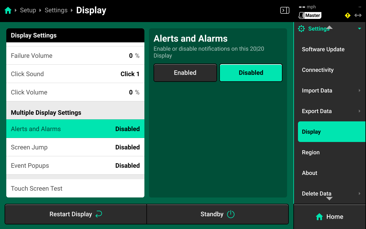
Disabling these settings prevents the display from notifying the user of important diagnostic information. Disable these settings only if there is a second display connected to the DBM with all alerts/alarms enabled.
Touch Screen Test
Press Touch Screen Test in the left window and again in the right window to run the touch screen test.

Draw on the screen to confirm touch screen functionality. Press and hold on the screen for 5 seconds to exit the test.
Region
Use the Region screen to change to change 20|20 language, toggle units of measure from Imperial to Metric, or change time zone.
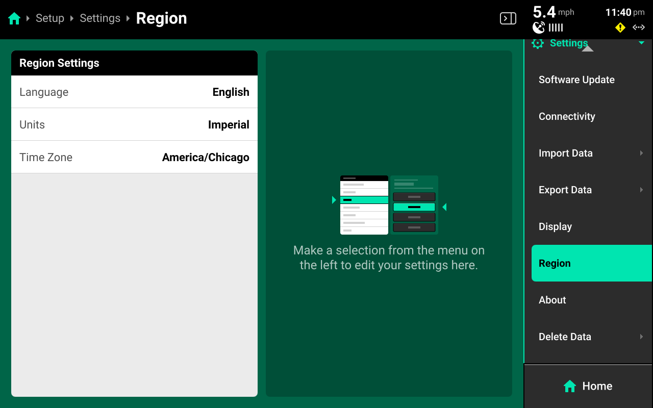
About
Use the About screen to view device information and disk usage for the DBM, display, and FVM (if connected).
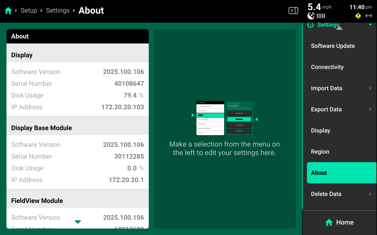
If DBM disk usage exceeds 70%, performance may begin to slow. If disk usage exceeds 70%, back up and then delete field data. See Delete Data for more details. Display disk usage is typically in the 70-80% range.
The about screen also allows the user to view the EULA or release notes for the currently installed software version.
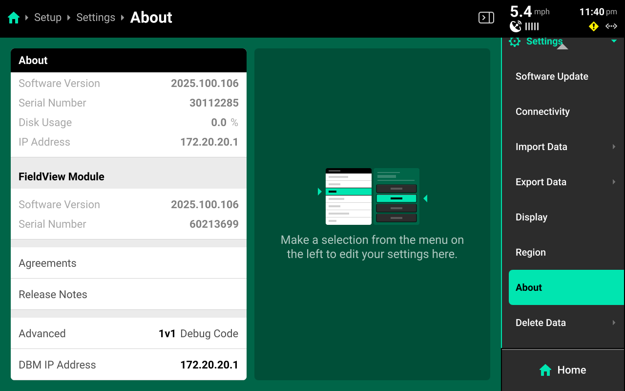
Press Reset EULA to force the display to show it again on the next boot up.
Advanced Users Only
The About screen may also be used to enter a Debug Code if advised by Precision Planting Product Support, or to change to IP address of the DBM.
Delete Data
Use the Delete Data screen to erase data from the 20|20.
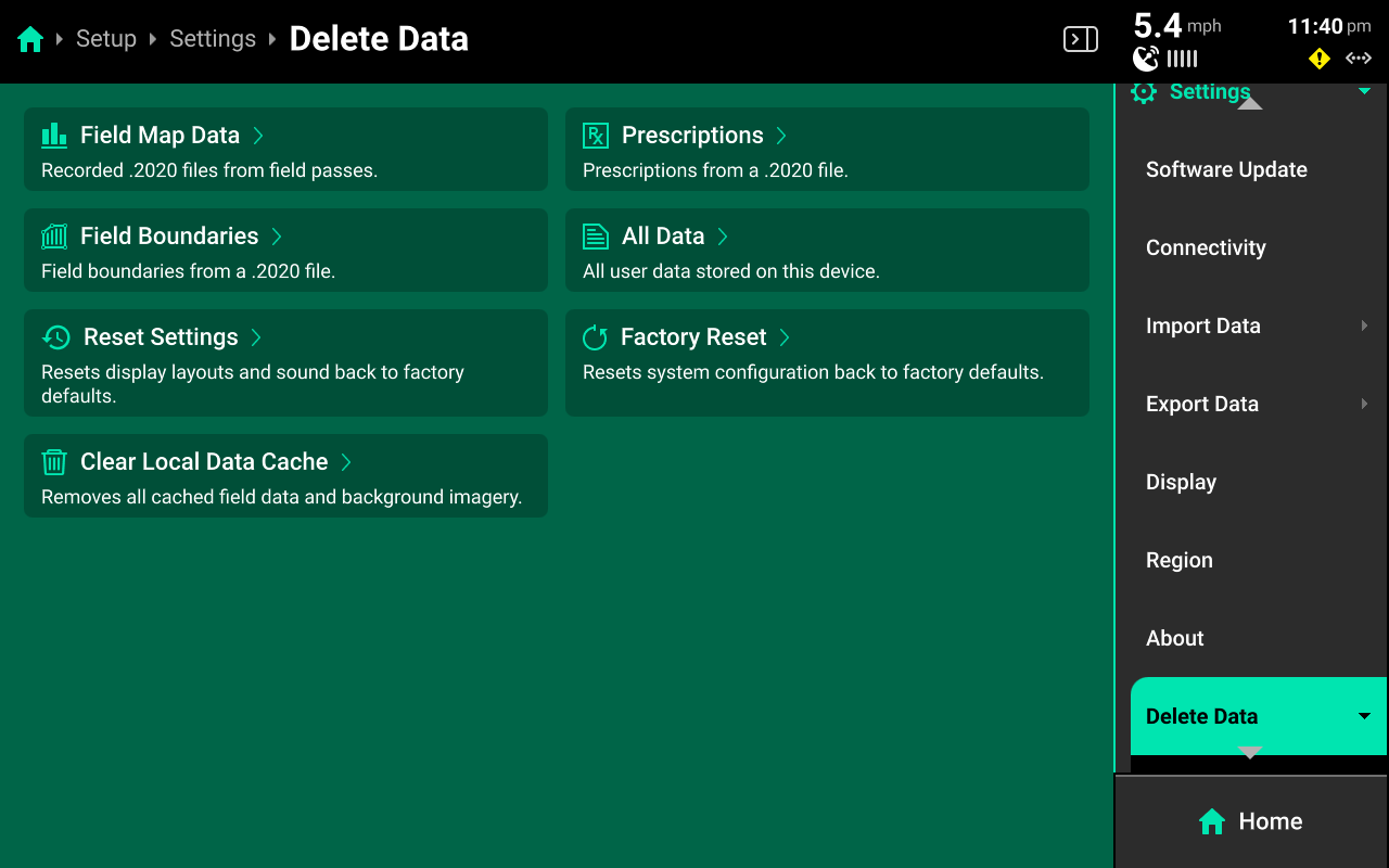
Clearing Device Settings
Select Factory Reset, All Data, Reset Settings, or Clear Local Data Cache and confirm on the popup to erase the selected type of data. Deleted data is not recoverable.
-
Deleting All Data will erase everything from the Gen 3, including field map data, screenshots and the restore configuration backup table.
-
Clearing the Local Data Cache is intended for use in troubleshooting situations and deletes data from the display only. DBM data will not be erased.
Deleting Maps / Prescriptions / Boundaries
Press Field Map Data, Prescriptions or Field Boundaries in the center or under Delete Data in the Navigation Menu to open a table which displays all files of the selected type. Press each desired file in the table or press Select All in the bottom left. Press Delete Selected (File Type) to erase the selected files from the 20|20. Deleted data is not recoverable.
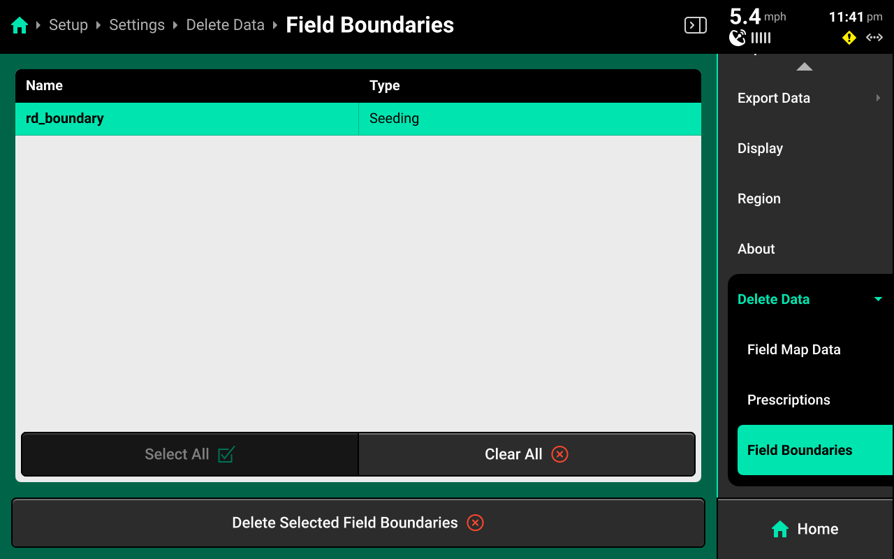
Appendix A
Basic Home Screen Metrics
Singulation - Measure of meter performance showing the percentage of seeds that are properly singulated - where the meter releases one seed rather than a skip or multiple.
SRI - Seed Release Index. SRI measures the consistency of seed spacing. It only takes into account properly singulated seeds so that skips and multiples are factored out of this measurement. It is a rolling average of the Seeds to Average value set in the seeding system alerts. The lower the number, the more consistent the seed spacing is. A theoretically perfect SRI score would be zero (0) and would indicate that every seed was placed in the exact correct position relative to its neighbors. Seed Release Index values over 32 mean that consistency of seed spacing is so erratic that it is considered to be random. Many factors, including meter type, meter performance, drive type, sensor location, ride quality, and seed characteristics may affect SRI. The expected SRI will be different for different planters with different meter and drive type combinations. Regardless of these differences, SRI commonly begins to have agronomic implications when it rises to 20 or higher. Because of this, the SRI button is configured by default to turn yellow when SRI reaches 20. This may be changed in the Limit Adjustments menu. Note that SRI on the planter will be higher than SRI on a MeterMax test stand
Down Force - This indicates the force acting on the gauge wheels. This is achieved by measuring the pressure against the depth stop created when the gauge wheels push against and converting that pressure into pounds of pressure. This is accomplished with a load cell installed on the row unit. For information on setting down force controls, see the relevant operators guide.
Down Force Average - This displays the average measurement of all load cell readings on the planter over a given period of time. This time period varies depending on the down force system installed.
Margin - This is the lowest measured load cell reading in a given period of time on one row (varies with down force system installed). The Margin value displayed on the home screen Down Force button is an average of this value across all load cell-equipped rows on the planter.
Ground Contact - The percentage of time the system can confirm that the gauge wheels have met the depth stop, which generally indicates that the row unit is planting at the depth to which it has been set.
Skips / Multiples - This metric identifies the breakdown of improperly singulated seeds among skips and multiples.
Good Ride - The Good Ride metric displays the percent of time when ride quality is sufficient not to interfere with seed spacing. This measurement provides assistance in diagnosing spacing errors caused by rough row unit ride. It is primarily used to help maximize speed while maintaining good SRI performance. When SRI is high and good ride is high, slowing down may improve SRI performance.
Average Spacing - This metric indicates the average spacing of seeds in the seed trench. It is calculated by dividing a number of seeds by the distance traveled while planting those seeds. It is not an indication of spacing accuracy.
 Appendix B
Event Codes
Last Updated - 11/26/2025
12000
No coverage source configured
No application system is configured to draw coverage on the coverage map. Swath control will not be operational.
12001
Hardware devices are redundantly specified
Hardware devices can only be specified once. Hardware devices will not operate properly until all duplicates are removed.
12002
The radar velocity sensor has not been calibrated
Radar has not been calibrated. The system will solely rely on GPS speed for mapping and system control.
12003
Hardware device(s) are not calibrated
Hardware device(s) have not been calibrated to enable proper control. System control will not be operational.
12004
No work state sensor has been configured
No work state sensor has been configured to determine frame position. Control systems will not be operational.
12005
Application system missing downstream row(s)
Row(s) exist that have not been set as downstream of the application system.
12006
Module has been assigned to a row not on the implement
Module(s) have been assigned to row number(s) that are higher than the implement
12007
Mixed Passive and Active Smart Connector(s)
A mixture of passive and active Smart Connector pin sets have been configured.
12008
Load cells have not been zeroed
Load cells have not been zeroed and must be zeroed for accurate measurement.
12009
PDM is required but not configured
A PDM has not been configured in the implement bus setup, but is required
12010
vDrive(s) in multiple applications
vDrive(s) have been configured in multiple applications
12011
Invalid Lift Manifold and Double Acting Cylinder Configuration
Each double acting cylinder must be assigned to a downstream row
12012
vDrive(s) are not calibrated
vDrive(s) do not have necessary calibration settings entered
12013
Rate Control Module(s) are not calibrated
Rate Control Module(s) do not have necessary calibration settings
12014
vApplyHD(s) in multiple applications
vApplyHD(s) have been configured in multiple applications
12015
Rate Control Module in multiple applications
Rate control module(s) have been configured in multiple applications
12016
Invalid Rate Section Assignment
Rate sections have been incorrectly configured for this implement.
12017
Swath Control Module pins in multiple applications
Swath control module pin(s) have been configured in multiple
12018
The Gyro has not been zeroed
The Gyro has not been zeroed. The system Gyro is used for rate control
12019
Invalid mSet/vSet Configuration
This mSet has been configured on the same row as a vSet.
12020
Invalid mSet/vDrive Configuration
This mSet has been configured on a row with no vDrive.
12021
Invalid Down Force Sensor
The selected down force sensor is incompatible with the selected row unit
12022
Invalid Cylinder
The selected down force cylinder is incompatible with the row unit
12023
Device Configured on Invalid Location
A module has been configured on a location that does not exist
12024
Multiple Pump Controllers
Flow Regulating Valve and Hydraulic Pump Control modules cannot both be added
12025
Invalid Control Sections
Rows have been used down stream that are not defined
12026
Mixed Passive and Active Blockage Inputs(s)
A mixture of passive and active Blockage Inputs have been configured.
12027
Mixed Passive and Active BXM(s)
A mixture of passive and active BXM pin sets have been configured.
10000
Cloud Connection Failed
The username and password are not valid.
10001
Low GPS Satellite Count
The GPS data is unreliable due to a lack of satellites.
10002
Low GPS Quality
The GPS communication quality is low.
10003
High GPS BAUD Rate Usage
The GPS communication bus usage is greater than 90%. This condition could cause inaccurate mapping and control.
10004
Daisy Chain Grounded
There is a daisy chain short in the wiring harness. The detected configuration may not be correct.
10005
Daisy Chain Broken
There is a daisy chain break in the wiring harness. The detected configuration may not be correct.
10006
Unknown Implement BUS Module
An unknown Implement BUS Module has been detected. Check harness for damage.
10007
Intermittent Signal
The Lift Switch is exhibiting erratic behavior.
10008
Optics Damaged
Signal error detected.
10009
Lens Blocked
Lens blockage detected
10010
Erratic Signal Readings
Signal error detected.
10011
Unstable Gyro
Unstable Gyro. Turn rate compensation is disabled.
10120
No Accelerometer Detected
The SRM in the PDM does not have an accelerometer. Turn rate compensation is disabled.
10012
Over Voltage
The Smart Connector has been shut down due to an internal over-voltage condition.
10013
Planter Harness Short Circuit
The Smart Connector has been shut down due to an apparent short circuit in the planter harnessing.
10014
Negative Current
The Smart Connector has been shut down due to a negative current reading in the planter harness.
10017
( Sensor ) Under Voltage
The Smart Connector is unable to supply 8V power to the seed tube sensors.
11021
Driver Overcurrent
The Nozzle Control Module has been shut down due to an driver overcurrent fault.
10015
Seed Sensor Obstruction
An obstruction has been detected on the seed sensor.
10016
Persisting Seed Sensor Obstruction
An obstruction has been detected on the seed sensor. Seed sensing will not be accurate.
10093
SRM Aux ID Unexpected Change
During operation, the Aux ID on the SRM has changed to another ID unexpectedly.
100017
Expected Devices are Missing
Verify that the configuration and the diagnose page is correct.
100018
Module Update Failed
Module Update Failed
100019
Module Unexpected Reset
Module reset when the command was not sent to do so
10020
Supply Voltage is Low
Supply voltage has dropped to between 9.5V and 10.5V
10021
Supply Voltage is Critically Low
Supply voltage has dropped below 9.5V
10022
Open Circuit
Open circuit detected in harnessing or module
10113
Short Circuit
Short circuit detected in harnessing or module
10118
Multiple Devices Detected
Multiple devices of the same type have been plugged into with same jumper color
10119
Module Failed to Reset
Module did not respond to commanded reset
10125
High Current
Module has been shutdown due to excessive current draw.
10126
High Current
Module has been shutdown due to excessive current draw.
10127
Duty Cycle Max
Duty cycle at max, verify max duty cycle setting.
10128
Motor Speed Not Detected
No motor speed detected, verify hydraulic pressure and check speed pickup.
10129
Product Applying
Motor speed detected when command is zero.
10023
Motor Unstable
Poor motor stability is being detected.
10024
Motor at Minimum Speed
Motor operating at minimum speed.
10025
Current Draw High
The current draw is too high.
10026
Motor Fault, Soft Jam
Motor jammed, attempting to clear jam.
10027
Motor Fault, Hard Jam
Motor stopped, unable to clear jam.
10028
Encoder Not Detected
The encoder has stopped responding.
10029
Motor High Temperature
The motor is reporting an over-temperature.
10121
Flow Reducer Cannot Reach Target
The Flow Reducer is not able to achieve target.
10122
Accessory Port Over Current
The accessory port has been shut down due to excessive current draw.
10030
Overcurrent Shutdown
Shutdown due to high current draw.
10031
Flow Reducer Cannot Reach Target
The Flow Reducer is not able to achieve target.
10032
No Belt Speed Detected
No belt speed was detected while current draw is within normal range.
10033
Delivery Sensor Weak Signal
The sensor may have difficulty detecting seeds due to a weak sensor signal from the seed delivery side sensor.
10034
Return Sensor Weak Signal
The sensor may have difficulty detecting seeds due to a weak sensor signal from the belt return side sensor.
10035
Belt Missing Flight
Missing belt flight has been detected.
10036
Motor Command Saturated
The module is commanding full speed, and may not be keeping up with ground speed.
10123
Overcurrent Shutdown
Shutdown due to high current draw.
10037
Dispenser Gate Jammed
The dispenser gate is jammed.
10038
Level Sensor Calibration Fail
The level sensor failed to calibrate.
10092
Level Sensor Missing
The level sensor is not detected
10094
Motor Unstable
Poor motor stability is being detected.
10095
Motor at Minimum Speed
Motor operating at minimum speed.
10096
Motor Fault, Soft Jam
Motor jammed, attempting to clear jam.
10097
Motor Fault, Hard Jam
Motor stopped, unable to clear jam.
10098
Encoder Not Detected
The encoder has stopped responding.
10099
Motor High Temperature
The motor is reporting an over-temperature.
10043
Product Leaking
Motor speed or ball valve open detected when command is zero.
10048
Pressure High
Pressure has exceeded maximum pump pressure setting, check pressure regulator.
10049
Ball Stuck
Ball valve not able to move when commanded.
10050
FlowSense Signal Error
EM FlowSense is reporting a signal error. Flow readings are not accurate. Replace the EM FlowSense.
10051
Turbine Marginal Overspeed
Low flow turbine is being run at a speed marginally over specification.
10052
Turbine Overspeed
Low flow turbine is being run at a speed over specification.
10091
Turbine Stuck
Low flow turbine inside module is jammed. Loss of accuracy at current rate.
10053
Total Flow Turbine Jammed
Total flow turbine not reporting any flow, so the ball position will be restricted to lower rates.
10054
Low Flow Turbine Jammed
Low flow turbine inside module is jammed.
11019
Nozzle Solenoid Partially Stuck
The solenoid inside the nozzle body is stuck partially open.
11020
Nozzle Solenoid Fully Stuck
The solenoid inside the nozzle body is stuck. Flow rate may be incorrect in this state.
10114
No Flow Feedback
The HD is configured to receive flow feedback from EM FlowSense but is not receiving it.
10111
Dual Pressure Module Insufficient Lift Pressure
Insufficient lift pressure detected
10112
Dual Pressure Module Insufficient Down Pressure
Insufficient downward pressure detected
11017
Driver Fault
The Sprayer Control Module has been shut down due to an internal driver fault.
11018
Driver Overcurrent
The Sprayer Control Module has been shut down due to an driver overcurrent fault.
10117
Pump Pressure Low
The pump has been turned off due to low pressure.
10055
High Electrical Noise On Sensor
High electrical noise level on sensor circuit. Check YieldSense Module & Flow sensor connections, as well as proximity to radio antenna cables.
10056
Flow Sensor Temperature Out Of Range
The temperature of the flow sensor is outside the expected range. Please check the flow sensor and flow sensor harness connections.
10057
Flow Sensor Voltage Out Of Range
Flow Sensor voltage out of range. Check connectors or replace flow sensor.
10058
No Crud Brush Detected
No crud brush detected on chain assembly. Please check & replace.
10059
Crud Brush Damaged
The crud brush is damaged or worn beyond its useful life. Please check & replace.
10060
Elevator Chain Missing Or Damaged
Elevator chain missing or broken paddles. Inspect and possibly repair chain.
10061
Flow Sensor Not Connected
Flow Sensor not connected. Check YieldSense Module & Flow Sensor connections & harnesses.
10062
Crud Build-up Flow Sensor
Possible crud build-up on flow sensor surface. Inspect & clean.
10063
Can't Detect Grain Property Paddle
Unable to detect the Grain Property Paddle. Verify that it is installed in the correct location and not damaged.
10064
Flow Sensor Signal Fault
A faulty flow sensor signal was detected. Please check the flow sensor and flow sensor harness.
10065
Moisture Sensor Not Changing
Moisture Sensor value not changing. Check the moisture sensor for blockage and inspect the moisture sensor motor fuse.
10066
Sensor Low Load Variation
The sensor is not responding. Ensure that it is properly installed. If problem persists, replace
10067
Sensor Signal Failure
The sensor is reporting a signal failure. Replace the sensor.
10068
Sensor Signal Failure
The sensor on is reporting a signal error. Lift the planter, inspect the depth linkage and sensor, then re-zero. If this error persists, replace.
10069
Sensor Zero Error
The sensor has a poor zero value. Raise the planter and re-zero all rows.
10070
Sensor Erratic Signal
The sensor is reporting an erratic signal.
10071
Sensor Signal Failure
The sensor is reporting a signal failure. Replace the sensor.
10072
Sensor Excessive Reading
The sensor is reporting an excessive positive load value. Please check row unit for damage.
10110
Insufficient Sensors
The solenoid section is reporting that it does not have enough sensors for automatic control
10073
Target Pressure
Unable to reach target pressure.
10074
Target Force
Controller is unable to reach target closing force.
10075
Supply Pressure Low
Supply pressure is low at the valve block. Confirm proper connection to tractor hydraulics.
10076
High Current
Module is drawing higher than expected current.
10077
No Movement
Module is not detecting any movement when it is being commanded.
10100
Range Calibration Invalid
Module has an invalid range calibration value.
10101
Offset Calibration Invalid
Module has an invalid offset calibration value.
10078
Position Unknown
Module unable to determine position.
10079
DBM Key Switch Voltage Low
The DBM is detecting a low keyswitch input voltage.
10080
DBM Battery not Charged
The DBM battery is not fully charged. Leave the DBM connected to a power source to finish charging. Please contact support if this issue persists.
10115
Battery Charging Fault
Battery Charging Fault
10081
DBM AM57 Thermal Warning
The DBM is too warm. Move the DBM to a cooler location to prevent shutdown
10102
DBM Update Failed
DBM system software update failed.
10105
Configuration Invalid
A value was entered that is out of the acceptable range or is invalid. Verify the value you entered is correct.
10106
Internal Storage Failure
Internal data storage failure has occurred. Any data collected will be lost. You can reboot to attempt to fix this problem.
10107
DBM Serial Number Missing
The DBM Serial Number is not set. Please set the serial number.
10109
WiFi Not Functional
Internal issue with WiFi. You may be unable to connect to the WiFi, or connect to a hotspot.
10103
Display Storage Issue
Internal storage could not be updated. If you operate the 20/20 with this problem performance may be degraded.
10104
Display Disk Mismatch
An internal storage size mismatch problem has been detected. If you operate the 20/20 with this problem performance may be degraded.
10108
FVM Storage Full
The FVM storage is nearly full. You must delete the FVM storage
10082
DBM Tractor Voltage Low
The DBM is detecting a low tractor input voltage.
10083
Radar Missing While Moving
The Radar speed is missing while the GPS shows movement.
10084
GPS and Radar Speed Mismatch
GPS and Radar speeds differ by more than 0.5 mph.
10085
Internal Storage Full
The internal data storage area is nearly full. You MUST go to the Setup | Data | Export | FieldMap page to export field map data to a USB drive and then delete the data to free up space for new field map information.
10086
DBM Serial Number Unset
The DBM Serial Number is not set. Please set the serial number.
10087
Turn Rate Mismatch
The gyro turning rate does not match the turning rate provided by the GPS
10088
No Acceleration Detected
The planter started moving but no acceleration was detected. Motors were started based upon a speed being detected for several seconds.
10089
Radar Unstable
The Radar speed is either changing rapidly or is outside the expected range compared to the GPS speed.
10090
Intermittent Work State Sensor
The work state sensor has shown lifted for a short amount of time.
 Appendix C
Precision Planting continues to support Legacy-style Gen 3 20|20 software (2021.0.0 - 2025.0.0). Due to bug fixes and built-in hardware safeguards, it is strongly recommended for all Legacy software users to update to 2025.0.0 software. Users of versions older than 2021.0.0 will be asked to update for any support beyond basic troubleshooting.
Observe the following guidelines when updating from older Gen 3 20|20 software to 2026.0 or newer software.
- Always export device and account configs to an external backup before updating software. Panorama users may also download Gen 3 20|20 configs using field maps from previous years.
- When updating from 2021.0.0 - 2025.0.0 software to 2026.0.0 :
- Ensure to set up CAN / Ethernet Modules.
- Liquid systems will need to be set up again. Record / back up liquid system hardware layouts and pump calibration values to streamline setup.
- Rebuild all Home Screen configurations.
- When updating from software older than 2021.0.0, All Equipment Profiles, System Hardware, and Prescriptions / Boundaries will need to be set up from scratch or reimported. Record all relevant information before updating to streamline setup.
- When backdating from 2026.0.0 to 2025.0.0 software, Equipment Profiles and System Hardware will need to be set up from scratch.
- If updating to Limited Release software 2026.1.0 from any older version, the user must update to 2026.0.0 first.
- Due to file system changes, any Gen 3 20|20 that is updated to Limited Release software 2026.1.0 will be unable to backdate to any software older than 2026.0.0.